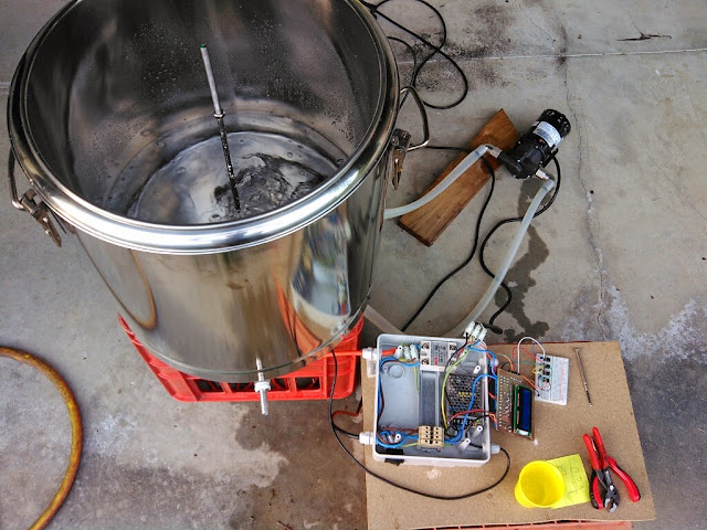
In order to have a threaded rod in the center of the pot and malt pipe and at the same time a camlock sealing I have used a bigger 3/4" camlock and the rod trough it. On the bottom of the main pot a Y fitting is used to connect the pump.
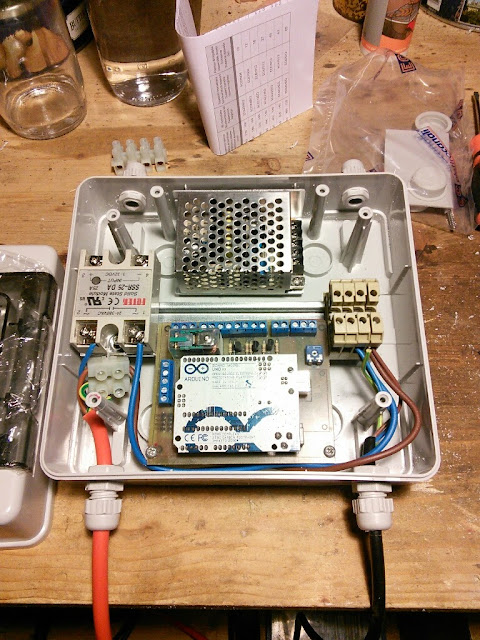
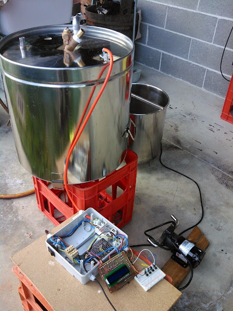
Here some picture that explain better the solution
Already tested with some water and seems OK
http://youtu.be/IOFzzH10K78'>
http://youtu.be/IOFzzH10K78
What do you think about?
Davide


")