Starting an Electric Brew control panel for AG brewing

Australia & New Zealand Homebrewing Forum

Help Support Australia & New Zealand Homebrewing Forum:

This site may earn a commission from merchant affiliate links, including eBay, Amazon, and others.
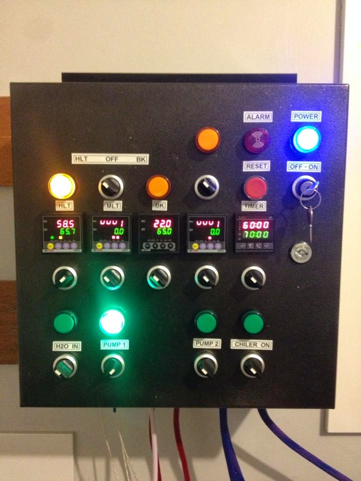
Cool, well I might do that. I can integrate the Reset button and alarm light as I bought an illuminated button. That should free up a hole to add another switch. Now to figure out how to wire up the switch...? Any suggestions?
 
With my control panel I've allowed for an upgrade to a stand alone HERMS?RIMS unit with a twist..

since my IN is only 20amps which i've allowed for my elements pumps etc.. I've wired up my PID (second on the right) to output the SSR pulse to a port on the bottom of the panel instead of 240v for controlling the element directly.
From this I'll build a full stand alone HERMS pot with element + SSR and the power cord (probably 10amp) going to a separate 10amp socket in my brewery..

This way my control panel doesn't require any further rewiring I can just connect the HERMS to the SSR output connector on my panel and off we go.. suits my power restriction in my brewery anyway until i upgrade to a 40amp plug THEN i need some rewiring..


wettest1.jpg
 
Cool, good idea. I was going to look at a HERMS pot but I think the 3v system is enough for the moment. I have those plug / screw connectors from a few pages back if you want a cheap set to connect the cables to the boxes.

I was going to do a chiller switch as well but i'll have to wait on that one.

What do you guys think, Should I grab a Chronical 26L fermenter or a Brew Bucket and a therminator? I have about $500 to spend. I had to cancel the therminator a while ago and I was going to use the HERMS coil for both HERMS and an immersion chiller.
 
So here is my next problem... I think I need to bash in the side of the keg.

I should have sat the plate on the side of the keg to make sure it was flat before punching the element hole.

Should I use a block of metal on the inside to squash the metal flat against it? I'm worried about scratching the inside of the vessel

1406605829318.jpg


1406605846060.jpg
 
I had some old silicone around too..

I'm wondering if some silicone tape on the thread and an o-ring inside would help in terms of sealing too?

1406606448352.jpg
 
I have you seen the enclosures that I used ... surely it would be easier to just grab some new enclosures rather then try and flatten the side of the keg?
 
Yours are great, and if I hadn't bought anything i'd have gone for them. But as it is i'll make this work. One of my kegs is bashed around so much already you'd think im straightening it out!
 
It's in their instructions to help make sure the electric side is watertight, not the wort side.

Although if you aren't trying to seal inside the vessel you must be expecting it to get into the gap with the heating element and the o ring on the outside...?

I have Pink High density silicone tape, is that ok?
 
If its anything like mine, the silicone is inside the element housing not the pot.
 
Yep that's right. Just finished reading from the linked post TheWiggman, I can see why you capitalized it! I really hope I dont have such a crappy introduction, I hope your off an brewing now :)

Anyone have an opinion on the Brew bucket and therminator or the Chronical fermenter? im so tempted for the fancier fermenter...
 
Bone dry :) that was until I forgot to shut off the tap and the whole thing overflowed! Made me panic for a few seconds..

1406620273409.jpg


1406620291347.jpg


1406620309860.jpg
 
sjp770 said:
Bone dry :) that was until I forgot to shut off the tap and the whole thing overflowed! Made me panic for a few seconds..
Have you made a weep hole under your control box just in case of leakage?

Gav
 
Yep, will do. I saw that on the highly coveted triclover heater enclosure.
 
Picked up the panel mount outlets for the pumps and metal glands for the heating cables and mains.

I'm not doing a fully removable cable for mains, I'm not sure why its needed? Mine will be like any normal appliance, a fixed power lead with a plug on the end.

Now I just need to source the 25A gear.

1406690703958.jpg
 
Temp probe holders mounted and pump outlets. Repaint has come up better but needs another coat. Thinking of applying sideways instead of up and down...

1406705420255.jpg


1406705483438.jpg
 
So I'm sick of this paint. With all the holes its hard to apply it smoothly in an even coat.I think unless it dries better than it looks now I'll strip it and get it done in automotive paint or powder coated.

Here you can see the leads plugged in for the temp probes, these are the pre done probe cables from Auber. The connectors are a bit fiddly but one on they seem tight. I can see why Kal went with XLR connectors.

In that pic there is a hole for the metal gland im using but I need to go back to the sparky tomorrow as they should have come with nuts for the inside. Hoping they were in the bottom of the tray of glands...

1406729581264.jpg
 
Paint job looks OK in person and feels nice and hard, unlike the first time it was painted.

Pic shows up a lot of faults. If I could spray it on I'd be OK.

Last switch arrived for the front, the three way switch go lost in the mail the first time.

The metal mains gland has been installed too. Needed to pickup nuts for the back as they weren't included, electrical wholesaler threw them in for me :)

1406798012051.jpg
 
Back
Top