Stc 1000 Temp Controller

Australia & New Zealand Homebrewing Forum

Help Support Australia & New Zealand Homebrewing Forum:

This site may earn a commission from merchant affiliate links, including eBay, Amazon, and others.
Hmmm........ after a close look I would make sure the sensor conductors are clamped by the screw terminals in the unit, Dont push the wires in so far that the insulation is in the clamp of screw terminal just the conductor.

They will go into alarm state if the sensor circuit goes open circuit.


Hope this helps,

Screwy
 
Thanks guys, have checked the sensor conductors and it is only the wires going into the clamps. I have a mate who has one set up so will see if I can borrow his to test it out. If not I'll go to Jaycar next week and get a resistor to test it with.

Really appreciate the help with this one so cheers!
 
Well tried the resistor instead of the sensor, found one in a broken toy in the spirit of DIY thriftiness and still have the same problem so have contacted the seller and will hopefully get a replacement. If not I'll be shelling out another lobster and might order a couple so I have a back up! Thanks again forthe tips.
 
Amber Fluid said:
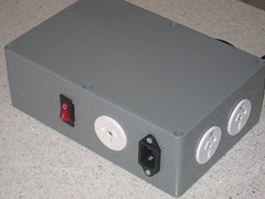
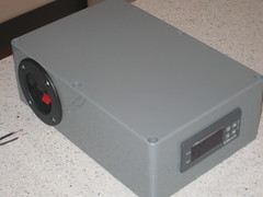
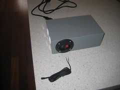
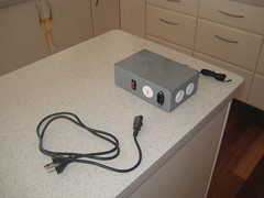
Here is my 3rd unit. I was wanting one that I could remove all cords from to make it easier to move the keezer.

I have used an IEC power connection for the power. A recessed speaker connection for the probe and included a 240v power supply that switches on/off via a rocker switch that I use for a fan (or anything else).

6451494337_1357d9dbf2_m.jpg


6451497459_c74ddd3d3c_m.jpg


6451484607_1b5dc9d6ab_m.jpg


6451481117_6c0571965a_m.jpg
Roughly how I did my first Temp Mates, but I used an RCA plug for the sensor. Much prefer your speaker connector, or perhaps a smaller one if I could find it.

The reason I started doing my STCs without the IEC connector, power switch or the removable sensors was because it took so long to do the case/mods etc and when you're dealing with a 20$ piece of electronics I didn't want to spend so much time on the build :)

I think if I was to do another I would use the switched skirting board GPOs for the output, probably easier to mount than the flush mount sockets, and you get the switches too. And then perhaps I could use a smaller case.
 
Hi guys,

I don't have any close sparky mates so I was hoping someone might take a glance at my wiring job and offer their appraisal.

I followed this wiring diagram and I've triple checked that my wiring matches it (with the exception of slight difference in the terminal block):

stc_1000_wiringdiagram_resized-50.jpg
Edit: This diagram shows power in to 6 & 8 and out of 5 & 7, whereas it should be the opposite, as explained here and here, and as shown in the wiring diagram in this post. Both configurations work but the latter is technically correct.

My wiring (with highlights for clarity):

IMG_0255-doc-small.jpg
 
I'm not a sparky but I wired mine up last night going off the other thread, which is pinned in this forum and I think that you might find that your brown cable into ports 6 & 8 should be into 5 & 7 and the outgoing power for your heating should be out of 6 and cooling out of 8

I did a quick test with mine last night, hooked the cooling up to a fan, and used 2 glasses of water for warm and cold temperatures worked fine
 
Tahoose said:
I'm not a sparky but I wired mine up last night going off the other thread, which is pinned in this forum and I think that you might find that your brown cable into ports 6 & 8 should be into 5 & 7 and the outgoing power for your heating should be out of 6 and cooling out of 8

I did a quick test with mine last night, hooked the cooling up to a fan, and used 2 glasses of water for warm and cold temperatures worked fine
Thanks, Tahoose. Congrats on getting yours up and running. I used that thread too (plus a bunch of others - lots of instructions dispersed everywhere) but felt I the wiring diagram I was going off was referenced the most and confirmed as correct.

But ahhh... that wiring diagram is wrong? Anyone else care to chime in here?
 
I've just gone back a couple of pages and there are photos that match your diagram and I'm assuming that these are pics of people's working stc-1000's

So now I'm a little confused... There is the possibility that 5 in and 6 out works and that 6in and 5 our works also... The same for 7&8

All I know is that I went by the other thread and used qld Kevs diagram for a double reference and it works.. :) I'm only set up for cooling atm, don't need heat for a month or two yet
 
I was wondering the same thing. I.e. whether in/out direction is not important. I looked up 'relay switch', as someone else explained the ports to work as, but couldn't figure it out. Hoping someone who actually knows how these things work can help us out... I think I'll hold off testing mine until then.
 
Technically 5 & 7 are you AC "in" and 6 & 8 are AC "out " to your fridge/heater.
 
It doesn't really matter either way should work.
 
Appreciate the responses guys. Hoping for a slightly more definitive answer before I switch this thing on or re-wire it - anyone else got any comments on the whole 5/7, 6/8 arrangement? Cheers.
 
Yes, but the 'technically' part suggested, to me, that it might work in another configuration too (i.e. how mine is currently wired). If it's only a technicality and it'll work either way I'd sooner leave it and go with what I've already done. Alternatively, can you explain why that way is technically correct?

It'd also be good to know if that wiring diagram (which I used) is incorrect so I can remove it from my post and possibly try to get the other ones like it removed so people don't have these issues in future.
 
Yes it will work the way you have it wired.

Technically the "in" or live wire should be conected to the switching pole ( the dot that the line is connected to ). The switched pole is the dot that the "out" or switched active is connected to.

It is the way that schematic diagrams are drawn. The drawing on the stc shows a single pole switch. If it was a double pole switch the pic would show another dot above the output and the diag line would conect to either the top or bottom pole
2014-01-31 15.27.27.jpg
 
Many thanks for the detailed explanation. I see what you mean about the switching/switched poles on the diagram and why the port layout you've explained it is technically correct. And I also see why the way I've wired it will work. I'm wiring up one more (for another brewing location) which I'll do the technically correct way, as you've explained, but I think I'll leave the one I've done and possibly just put a note about this on it.

Cheers!
 
wood88 said:
Yep looks like its all correct to me.
I changed it a bit as i found the diagram might be a bit confusing for first timers.
Bit of a quick job so its a bit messy, but everyone should get the point.

Cheers
attachicon.gif
stc_1000.jpg
Thanks to Bindibagi for posting the diagram and even more thanks to wood88 for re-drawing it in a way I could understand better.

Just wired mine up today and I'm so pleased :D

I love the way it's used as an independent unit without hardwiring in the fridge or heat belt. Great if the fridge ever fails, just plug in another, no fuss.

Think I might invest in a backup STC 1000 at some point though.
 

Latest posts

Back
Top