Matho's controller

Australia & New Zealand Homebrewing Forum

Help Support Australia & New Zealand Homebrewing Forum:

This site may earn a commission from merchant affiliate links, including eBay, Amazon, and others.
Hi All,

Hopefully this is the correct place to post this question.

I got into the homebrew world through cider making which I do every year using the apples & pears from relations gardens, roadside fruit etc. I also love beer and decided that I want to get into brewing so am in the process of building a braumeister clone using the kit that Lael is organising in the bulk buys.

If you glance at the non-beer brewing section of this forum you will find that it is common for people to be unhappy with their cider because it is too dry and normally too acidic (the sugar masks the acid). All ciders naturally will finish around 1.000 sg unless some action is taken to prevent it; commercial ciders are generally around 1014 (even the ones which have dry on the label!).

Pasteurising of ciders is one of the more common practises worldwide, the other common routes are sterile filtration or chemicals both of which are not really suited to the homebrewer. The major drawback of pasteurising is that it is almost always overdone leaving the cider to have a cooked taste.

In comes the mathos controller. Do people think it would be difficult to add another function to the controller to calculate pasteurising units and give an audible alarm when they have been reached? Here are two links which detail exactly what is required:

https://groups.google.com/forum/#!topic/cider-workshop/3mM4sIEkVJk
https://groups.google.com/forum/#!topic/cider-workshop/rJjxsXSzLl0/discussion

I think it would be an amazing feature to have. I am imagining you would have a second temperature probe measuring the temperature inside the bottle which would provide the feedback to the controller.

Cheers,

Fergal.
 
Good idea. I've pasteurised cider with my machine a couple of times. Works well. Takes a few weeks for the cider to return to normal taste, but then is delicious. I haven't measured inside a bottle yet. There would be differences as one is under pressure (the cider) and the open bottle would not be. I've tended to do 78C for ten mins. Which should be quite overkill, but worked well for me.
 
It will definately be used for pastuerising one way or another thats for sure. I was just wondering if the guys who were doing the programming thought it might be a useful thing to add to the current program? Using the equations for PU's in those links I suppose it would only be a matter of working out how long your system takes to reach 50 PU's and then following the exact same sequence each time. Thought it would be kind of cool to see the units couting up on the screen though!
 
Margin to implement is purely down to code space on the arduino, I"m sure the ArdBir team have a whole list of add-ons they'd more than love to load up, but where it's at now, most users are using a standard Arduino. I know the controller build Lael has been scouring the world for, for parts to complete will be using the Arduino Mega, which has ample room to add further features. These could quite easily be added as modules to the current ArdBir release. Obviously The controller lends itself to more than just brewing, pastuerising and yogurt are two that quickly come to mind. I'm sure somewhere down the track, one of the many smart cookies using this controller in one of 7 or 8 countries around the world will decide to dedicate some code to it. Patience it will all happen.

Ed: Almost missed it 1500 posts, I need to find something else to do that's way too many ... maybe I should drink more.
 
MaxN68 said:
Grainfather powered ArdBir. Great idea.
Finally have it in a suitable box courtesy of some dumpster diving. The danger sign was already on the box.
The pump and arduino are fed from one 240V circuit while the heater comes from another hence the four power leads on the bottom. Still need to hook it neatly onto the GF.
Any update on the new firmware?

image.jpg
 
I have built my one controller based on the Daniel Xan schematic and everything has been working fine, except i have only used an 8v external power supply to power the unit. This has been fine as I'm not using a pump and 8v is enough to drive the SSR and led's. But I've just tried to add a 12v power supply connected through the VIN pin because I'm about to add recirculation, now my SSR is permanently on as well as the buzzer, screen is working fine.

I've been over my wiring and the available schematics and have found a bit of a problem, there seems to be multiple versions that have the diodes in a different direction.

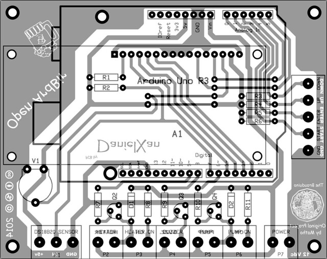
My PCB is connected as per the Daniel Xan pcb with the cathode to the 12v line and anode to heater on
OpnArdBir-lc by Mitch Dalton, on Flickr

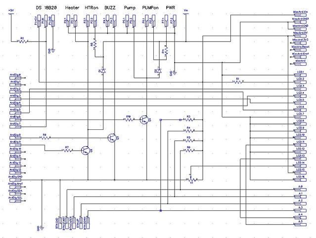
Also like this
Line diagram by Mitch Dalton, on Flickr

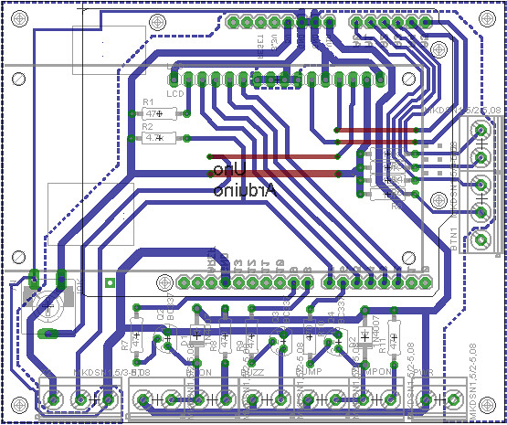
However i have found this on the Open Ardbir FB page with the diode reversed
danielxan 1 by Mitch Dalton, on Flickr

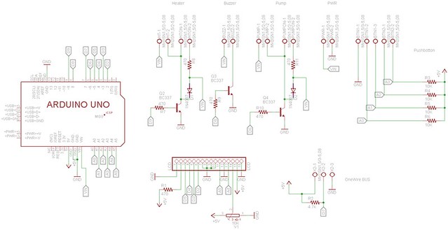
And lastly the schematic also shows this
Danielxan schematic by Mitch Dalton, on Flickr

These 4 images have all either come from the drop box files or the Open Ardbir FB page so I am taking them as legitimate it just puzzles me as to why there are differences and which drawing is correct?
 
Hi MitchD
The original Matho board is none of those. If you browse the early sections of this? Thread there are links to the circuit diagram and the construction manual for the board. The 12 v goes to the arduino power in and drives a few other bits and the relay for the pump. If you put 12v into the wrong part you will blow it up.

If you can not find schematic PM me and I will send it to you
James


Sent from my iPad using Tapatalk HD
 
Thanks, but i have already built my controller to the schematic posted above, which is an updated version of Mathos. The problem I have is which drawing is correct. I think I've nailed part of the problem down to the PN2222a transistor being opposite to a P2N2222a.
 
Hi Mitchd
Are you talking about D1 and D2?
They are LEDs they will only work one way round.

Mathos board had a diode across the coil of the relay to stop the back EMF blowing the transistor. Once again it can only work one way. The other the relay will not switch.

What, if any, board are you using?
What test equipment do you have? Multimeter?
What is your electronics knowledge level.
What spares do you have on hand.

With those answers I can suggest some tests to assist you.

I have blown up a few bits along the way fiddling with mine.

James

James


Sent from my iPad using Tapatalk HD
 
Yep d1 and d2 but they are not LEDs, don't know where you got that from?
As stated above i have used the Daniel Xan schematic to build my own using a blank prototype shield. Also stated above I have it working but when I go from 8v-12v it starts to have some issues.

Please re read my first post.

I am pretty sure the root of the problem is the transistors being backwards (my fault)

I am an electrician with experience with electronics, I am not worried about blowing things up but I really wanted to know why ardbir are posting multiple versions of the same product with mistakes.
 
Hi MitchD
Ok re read the posts and used a proper computer instead of the tablet. They are diodes and they are probably intended to stop the lines from being dragged to level s that may blow the transistors. The Matho's board does not have them. Transistors backwards may not really explain why it works on 8v and not at 12?
I do not have the parts list for the Danny board. The BC337 in the other one are fairly standard. I think the One I have currently is using the 2n2222. Either works if used correctly but I guess you are not planning to invert the signals in the sketch either. You could put a resistor around 800 to 1000ohm in as the load for the two SSRs and measure the pin in manual mode and see if it changes. can also measure the pin on the arduino at same time. If you have Leds in the other "Htr" on and Pump On then can probably just watch those and disconnect the SSRs? The normal SSRs are AC switches not DC and will not switch 12 v dc for a pump? That is why Matho used a relay. With Relay you need protection diode across the coil and it also put 240v on the main PCB which can catch you out if not careful.
Like any problem make it a linear process. measure the arduino pin then the transistor output then the SSR etc.
 
Thanks for your help. I have it all working now after completely rebuilding the shield because trying to remove 3 transistors wasn't going to happen, no matter how much solder sucking and goot wick.

Now that its sorted I've had a look/think and I think that my v1 board worked for heat only because the transistor stopped enough voltage through and the arduino board also played along to stop the ssr from being dragged low, when I added 12v there was just enough to drag the ssr down. I didn't look too hard into which component was doing me the favor. The transistors were PN2222a, not 2222a. Basically pins 1&3 are swapped, Matho posted about this around p45 and at 40c each they were quick to go.

The top 2 images I posted above are correct bottom 2 are wrong. Why the others exist/are in the open ardbir files is still a mystery and the reason the diode is there is exactly as you said above i just got tied up chasing one problem i seem to have found another.
 
Sorry if this is available somewhere else, but I could not find it... Are 4x20 LCDs with the HD44780 controller supported. Just got it all wired before I realized the pinouts were mostly wrong (schematic v. LCD). My LCD display pin out is:

1: Vss/GND
2: Vdd
3: Vo (contrast)
4: RS
5: R/~W
6: EN
7-14: DB0-DB7
15: Vdd for LED b/l
16: Vss for LED b/l

Thanks!
Dave
 
Yes, just change which include file for the screen is used in the build. If you don't it will still work but only the top two lines will be used.
Dave
 
Thanks for the reply, Dave. I had that part covered (include file LCD selection).

Can you or someone else send the pin descriptions? I still need to know which pin on the Arduino serves which function for the LCD.

Some are obvious, but I am not sure about the data and R/W and EN lines. If I had the datasheet for the LCD it was designed around, I could tell from that as well.

Dave A.
 
A quick search showed that the 2*20 and 4*20 have the same pinouts with 16 pins each. Look at the PCB diagram I posted above its the top image of the 4, it is correct BUT it is a mirror image so pin 1 of the screen goes to the first pin on the right and the rest will be in order working towards the left. This shield was designed to have a screen slot directly into it. Hope that helps
 
Hi Dave, have a look at the code and you will find the constructor (remember that Arduino is basically C++) instantiates an instance of a LCD class (which is overloaded) with the pinouts you specify (see https://www.arduino.cc/en/Reference/LiquidCrystalConstructor). The particular setup is defined in the pcb.h include file. Sorry to be a bit dismissive but I think it will help to look at the source code and get a feel for how it all fits together.
regards, Dave
 
EDIT: I saw Dave's post after I posted below. So, that gets me closer. I will need to review ArdBir source code and see which syntax it uses in the LCD function call. Then, see what pin numbers are passed to the function, and relate them to the pin functions at the link you sent.
Thanks
—-----------------
Pls forgive me, but I do not see the LCD pin functions, only the Arduino pins.

I did check the BOM, and the HD44780 is the controller family supported.

So, I need a link to an LCD data sheet that is known to work with the above schematic. That should solve my issue.

Thanks,
Dave
 
Back
Top