Added some thermal paste last night and the temps are now closer. Just inside 1 degree difference
I used a digital thermometer I grabbed from CraftBrewer and had another digital thermometer I grabbed from another homebrew store and none of them agree. The two digital temp probes are touching each other in the pot so theoretically should read almost the same, but just over 1 degree difference.
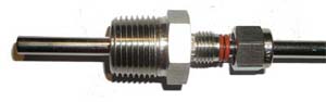
I am now thinking about getting
one of these and inserting my DS18B20 which is sheathed inside a stainless shield (from manufacturer). This should get me fast results at least.
So how do I test the accuracy of the DS18B20? Which thermometer do I trust as being correct? Or do I just assume the DS18B20 is accurate (or more to the point, it should be consistently inaccurate and I just adjust my systems) and move on with my project. :huh:


")