The Brauduino (Matho’s Controller) Build/Advice/Question Thread

Australia & New Zealand Homebrewing Forum

Help Support Australia & New Zealand Homebrewing Forum:

This site may earn a commission from merchant affiliate links, including eBay, Amazon, and others.
Great work Lael !!!

OK a bit of self promotion in there too.

I noticed one error in what I said but is a technical error of nomenclature.

And yes they are my chickens in the background learning how to wire the Brauduino! Actually they love the Malt ex mash.....

zwitter
 
lael said:
The same behaviour is not present in v 2.6.7 which is what most units shipped with.
Guys, just confirming that the user manual for v 2.6.7 is as per v 2.6.62 in the dropbox link here?
 
The Judge said:
Guys, just confirming that the user manual for v 2.6.7 is as per v 2.6.62 in the dropbox link here?
Thanks for that.

I downloaded the English version, but unfortunately it was all Greek to me.

I'm hoping that I won't need to get into any programing and that the controller will work out of the box. Can anyone confirm this.
 
Cervantes said:
Thanks for that.

I downloaded the English version, but unfortunately it was all Greek to me.

I'm hoping that I won't need to get into any programing and that the controller will work out of the box. Can anyone confirm this.
you will need to go through the setup process to set some values/params..
I think Lael/Zwitter had plans to make one of these guides/vids (along with a software update one)??
 
This might help if anyone else is trying to mount the temp probe in-line......I picked up a brass plug from the big green shed for $2 and bored out the inside by about 1-2mm on a mates lathe, and drilled a 10mm hole through the top:

IMG_0772.JPG


IMG_0775.JPG


IMG_0776.JPG


IMG_0777.JPG


IMG_0778.JPG
 
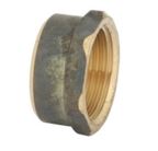
I didn't have the option of being able to bore out the inside of the 15mm plug so I am planning the following, I bought the parts yesterday and will drill it out today:


20mm cap (10mm hole drilled though this)
k0HwH1G.jpg


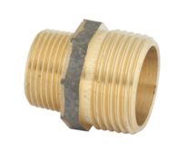
20mm x 15mm reducer
kUn6C4O.jpg


Then into the standard 1/2 BSP t-piece.

Similar result to BobCharlie in the end though just another option for those who do not have the ability to bore out the normal plug.

I also found these same parts on ebay from china which are on their way but the brass will work until they finally turn up.

ebay reducer and ebay cap
 
BobCharlie said:
This might help if anyone else is trying to mount the temp probe in-line......I picked up a brass plug from the big green shed for $2 and bored out the inside by about 1-2mm on a mates lathe, and drilled a 10mm hole through the top:
and when will you start selling these? ;)
 
So the "speaker cable" I got is figure 8 7.5 amp rated cable. Is this the same as the cable mentioned in the video for the SSR?
Also the brown flex cable doesn't say what amps it is. Would 10 amp be fine or should I go for the 20 amp?
As a side I got the 2.5mm twin and earth for the other wiring
Thanks
 
lespaul said:
So the "speaker cable" I got is figure 8 7.5 amp rated cable. Is this the same as the cable mentioned in the video for the SSR?
Can't remember what Lael/Zwitter mentioned in the vid but thats plenty as its only carrying a low voltage (12v) switching signal to the control side of the SSR to turn the SSR on/off on the load side

lespaul said:
Also the brown flex cable doesn't say what amps it is. Would 10 amp be fine or should I go for the 20 amp?
Thats purely for running the pump so 10Amp is plenty/overkill (even a March 809 pump only draws less than 1Amp)
 
Hey Lepaul

What SBOB said

The signal side of the SSRs from the PCB is milli amps. So bugger all and any small cable will do.

For the power feed to the power supply also very little current. I used 7.5Amp odd 240 v figure 8 and is over kill

For the power to and back from the relay for the pump use the 7.5Amp figure 8. It will be more than enough for any pump.

Only the main power in and heater out and the connections to the 240v side of the SSRs needs to be 20Amp

Zwitter
Sent from my iPad using Tapatalk HD
 
zwitter said:
Hey Lepaul


For the power feed to the power supply also very little current. I used 7.5Amp odd 240 v figure 8 and is over kill

For the power to and back from the relay for the pump use the 7.5Amp figure 8. It will be more than enough for any pump.

Zwitter
Sent from my iPad using Tapatalk HD
Just be very careful not to plug the heater into the pump socket. As that will draw more than the circuits can handle and fry the relay and cables.
Cheers
Bigmacthepunker
 
lael said:
Here we go:

A quick video to show you how to run through set up on your Brauduino Controller.

Cheers!

https://youtu.be/C_HDUacxeNs
Glad to see that I'm not alone with the invaid chars at the end of the line...
Haven't bothered looking through the code but I imagine its because its not clearing whatever was validly displayed there last


lael said:
Let me know if there is anything else you want to see / know how to do :)
Does that include pots, malt pipes and stainless mesh? ;)
 
lael said:
Here we go:

A quick video to show you how to run through set up on your Brauduino Controller.

Cheers!

https://youtu.be/C_HDUacxeNs

Let me know if there is anything else you want to see / know how to do :)
Thanks Lael

Can you explain what the 'Heat in Boil" setting means in the latest software?
What value should it be set at?

Almost finished a test run with water and looking forward to brewing my first beer with it..
 
SBOB said:
Glad to see that I'm not alone with the invaid chars at the end of the line...
Haven't bothered looking through the code but I imagine its because its not clearing whatever was validly displayed there last
so being both bored and OCD in equal parts this morning, the following is what you need to update in the code if you dont want to see the annoying extra character during the PID settings pages

- Open the ArdBir_2_8_3RC8.ino file with whatever version of the Arduino software you are using
- Navigate across the top to the file named 'LCD20x4_ENG.h' (assuming you are using the english language, if you aren't then I havent checked the others)
- Find the routine 'void PidSet(int pidSet, byte i)'
- Find the line (line 2 in the routine) that says 'lcd.setCursor(10, 2);'
- Update it to 'lcd.setCursor(9, 2);'
- Re 'Verify', and 'Upload' the code
(all settings will likely be wiped and need setting again, but the annoying extra character on all the PID pages should now be fixed)

I cant see anywhere in the code that indicates to me that this change will cause any issues, but it goes without saying that 'don't blame me if it breaks anything' ;) Looking at the history of the file it looks like this was broken back in Feb but hasnt been fixed/updated...

Pic attached to show the line needing updating
LCD20x4_ENG.jpg
 

Latest posts

Back
Top