Arduino Development Thread

Australia & New Zealand Homebrewing Forum

Help Support Australia & New Zealand Homebrewing Forum:

This site may earn a commission from merchant affiliate links, including eBay, Amazon, and others.
I have received some interest in my controller locally, and am thinking if there's enough interest I may put some sort of a kit together.

Full features are:
  • Up to 10 steps per mash program (each step contains a temperature and a time)
  • Number of steps configurable per program in the menu
  • 2 Preset mash programs (Zwickel's Ale, Zwickel's Lager) (possibility of more, or for changing the presets in the code (see below about open sourcing))
  • 2 Custom program slots (can load and save your entered program) (possibility for more than 2 custom slots(see open sourcing below), it just makes the menus a little longer to traverse)
  • PID controlled temperature
  • PID tuning parameters can be edited and saved for future use
  • Easy 3 button operation (left, right, select)
  • Code will be open sourced (when I decide on which license to use.... front-runners are BSD and GPLv2)
  • I'm *thinking* about incorporating the PID autotune library

Unlike Gryphon's HERM-IT controller, it won't be available pre-built. If you're after a prebuilt unit that is featured similarly to this one, check the HERM-IT out.
 
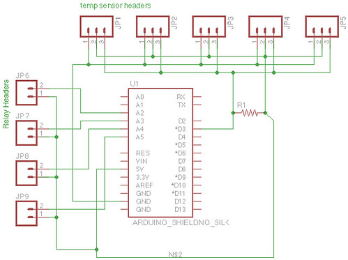
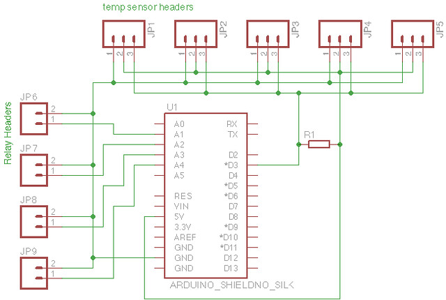
I've been looking into making a custom shield (more out of interest than necessity) and have come up with this schematic in Eagle:


arduferm_circuit by auvortex, on Flickr

I'm not 100% on the SSR relay control with Arduino though - I've got 5v connected to the +ve on the relay headers, and the negative to the pin which will control the SSR (they will be digital pins, defined in software). Do they look right?

I plan on changing those screw terminals to solder pads though, but that works well enough for a diagram I suppose.
I went the other way round, on my HERMS controller board, with the + connected to the arduino pin, and - connected to GND.

I also made it rather generic, with pin header style connections on the outer edge of the board, with just broken out connections so I could wire it how I like with jumpers.
396867_10151068860495792_368407514_n.jpg

I also added a few things I might use in other projects, like opto-isolated (with 4N25 optocoupler) BD135, a bunch of unconnected pull-up/pull-down resistor spots for push buttons etc., GND rail, V+ rail, specific connection for DS1820, LCD...
 
I get mine done through seeedstudio's fusion pcb service. They have a minimum of 10 PCBs per order.
 
I am just curious Vortex, unless I missed it earlier, why do you require 4 outputs? Are you going to use solid state relays only? Have you considered wireless control/monitoring with xbee or similar?

If you are getting boards made up then pack the features in there just in case I say..

edit : what about a display? You can get i2c lcds or a display slash interface from DealExtreme like the one on my fridge controller.
 
I have received some interest in my controller locally, and am thinking if there's enough interest I may put some sort of a kit together.
Hey Bonj,
I'm up for having a go at putting one together - will probably test my skills a bit but I've done STC's etc so I'll get there :lol: . How much are you planning on supplying as part of the kit? Have you had enough interest to continue at this stage?
 
I am just curious Vortex, unless I missed it earlier, why do you require 4 outputs? Are you going to use solid state relays only? Have you considered wireless control/monitoring with xbee or similar?

The plan is to control heating and cooling circuits for two separate fridges, so 4 circuits :) All SSR's. Haven't considered wireless, because the whole house has ethernet, and the fermentation fridges are next to a spare point. May as well use it :) Have PoE capability on that port too so will likely power the Arduino with that.

If you are getting boards made up then pack the features in there just in case I say..

edit : what about a display? You can get i2c lcds or a display slash interface from DealExtreme like the one on my fridge controller.

I have the 16x2 Freetronics LCD at the moment but as has been said it does use a lot of pins. I have seen the I2C displays since and they look good (larger display, key functionality and less pins); but I'm not out of pins yet anyway so I might look at changing to one of those displays down the track when I build the RIMS/HLT controller.
 
Hey Bonj,
I'm up for having a go at putting one together - will probably test my skills a bit but I've done STC's etc so I'll get there :lol: . How much are you planning on supplying as part of the kit? Have you had enough interest to continue at this stage?
At this stage, the kit will consist of just the PCB, and instructions on what other parts you will need, and how to wire up the PCB.
 
At this stage, the kit will consist of just the PCB, and instructions on what other parts you will need, and how to wire up the PCB.
Ok thanks mate, well I'm up for one if you decide to go ahead, I'll check the thread to see what happens. Looks like a cool way to do a HERMS.

:icon_cheers:
 
At this stage, the kit will consist of just the PCB, and instructions on what other parts you will need, and how to wire up the PCB.


Bonj,
You can put me down for a kit as well.

Would it be possible to control a ferment fridge as well similar to what Vortex is planning or should I keep it seperate?
 
The plan is to control heating and cooling circuits for two separate fridges, so 4 circuits :) All SSR's. Haven't considered wireless, because the whole house has ethernet, and the fermentation fridges are next to a spare point. May as well use it :) Have PoE capability on that port too so will likely power the Arduino with that.


I have the 16x2 Freetronics LCD at the moment but as has been said it does use a lot of pins. I have seen the I2C displays since and they look good (larger display, key functionality and less pins); but I'm not out of pins yet anyway so I might look at changing to one of those displays down the track when I build the RIMS/HLT controller.

Hi again Vortex,

I personally think that using SSRs to control fridges is a bit of overkill. Firstly SSRs generate about 1W of heat for every amp that passes through them, hence you may need heatsinks (unless you have a metal enclosure you can use). Secondly, they are large. Thirdly, they are expensive.

I would recommend that you use standard relays because they don't switch very regularly, require no heatsink, are cheaper and smaller.
Something like this will get you sorted in seconds and has the option of full isolation (if desired)
http://dx.com/p/arduino-compatible-4-chann...e-144762?item=2

I used this display/control combo, which only requires 3 pins to drive 8x 7 seg displays, 8x 2-colour LEDs and 8x buttons.
http://dx.com/p/8x-digital-tube-8x-key-8x-...e-81873?item=11
Arduino library - http://code.google.com/p/tm1638-library/

Be aware that if you are using Ethernet to connect directly to the arduino that you will get very close to running out of code space and maybe RAM because the Ethernet library requires a lot of resources especially if you plan on hosting any pages from the arduino itself. When you combine this with suitable PID control for your fridges (i recommend that you look at the source code of the uberfridge for fridge temperature control) you run out of space very quickly. Another thing to watch for is that the Ethernet library is not very stable in Arduino 1.0 so you should go straight to Arduino 1.0.1.

My fridge sits on over 29k code and uses the following libraries:

#include <stdlib.h>
#include <SPI.h>
#include <Ethernet.h>
#include <OneWire.h>
#include <DallasTemperature.h>
#include <TM1638.h>
#include <EEPROM.h>
#include <Wire.h>
#include <avr/wdt.h>

Note also that you will run out of pins more quickly than you think. My defs (digital):

0-1 = HW serial
2 =
3 = One-Wire BUS for temp sennsors
4 = SPI CS for SD CARD (this is built into the EtherTen)
5 = TM1638 DATA
6 = TM1638 CLOCK
7 = TM1638 STROBE
8 = Heater Output
9 = Cooler Output
10 = SPI CS for ETHERNET (Wiznet)
11-13 = SPI

Note that my display and all push buttons only use 3 pins! What are your pin definitions and how do you fit any control and the LCD in there?

My fridge generally keeps beer temps to within 0.15C of set point (measured from the side of the fermenter). I still need to fine-tune the code and PID settings but a little tolerance is okay. If you want a look at the data, let me know via PM.

EDIT: Graaaamah
 
I personally think that using SSRs to control fridges is a bit of overkill. Firstly SSRs generate about 1W of heat for every amp that passes through them, hence you may need heatsinks (unless you have a metal enclosure you can use). Secondly, they are large. Thirdly, they are expensive.

I would recommend that you use standard relays because they don't switch very regularly, require no heatsink, are cheaper and smaller.
Something like this will get you sorted in seconds and has the option of full isolation (if desired)
http://dx.com/p/arduino-compatible-4-chann...e-144762?item=2

To be honest, I thought SSR's were the only option for relays that worked with AC, though the research I was doing was based around the element in my RIMS system. The relay board does look like a good option though, so I'll definitely look at those a bit more closely. I was also considering SSR's because of how easy they are to work with (given that I'm very new to building circuits) but an add-on board like that is very attractive and probably not difficult to implement.

I used this display/control combo, which only requires 3 pins to drive 8x 7 seg displays, 8x 2-colour LEDs and 8x buttons.
http://dx.com/p/8x-digital-tube-8x-key-8x-...e-81873?item=11
Arduino library - http://code.google.com/p/tm1638-library/

Be aware that if you are using Ethernet to connect directly to the arduino that you will get very close to running out of code space and maybe RAM because the Ethernet library requires a lot of resources especially if you plan on hosting any pages from the arduino itself. When you combine this with suitable PID control for your fridges (i recommend that you look at the source code of the uberfridge for fridge temperature control) you run out of space very quickly. Another thing to watch for is that the Ethernet library is not very stable in Arduino 1.0 so you should go straight to Arduino 1.0.1.

I was worried about that as I haven't got an Ethernet capable Arduino as yet but had read that could be an issue. I'm planning for the controllers functionality over ethernet to be very limited - simply serving a single page with the current status (formatted as JSON for easy parsing on the server) that will be read by an external script on a server elsewhere in the house, and an automated process on the arduino to read from the same server to download it's settings.

It might be a case of "try it and see", but currently the relay control, OneWire temp reading etc is all in around 11k. Still some code to be written though and libraries to include as yet :)

Note also that you will run out of pins more quickly than you think. My defs (digital):

0-1 = HW serial
2 =
3 = One-Wire BUS for temp sennsors
4 = SPI CS for SD CARD (this is built into the EtherTen)
5 = TM1638 DATA
6 = TM1638 CLOCK
7 = TM1638 STROBE
8 = Heater Output
9 = Cooler Output
10 = SPI CS for ETHERNET (Wiznet)
11-13 = SPI

Note that my display and all push buttons only use 3 pins! What are your pin definitions and how do you fit any control and the LCD in there?

Again this was another concern. I mapped out what I think the pins would map to:
Code:
/* PinMap: 

 *

 * 1

 * 2

 * 3   One Wire Data

 * 4   LCD

 * 5   LCD

 * 6   LCD

 * 7   LCD

 * 8   LCD

 * 9   LCD

 * 10  ETH

 * 11  ETH

 * 12  ETH

 * 13  ETH

 * 14

 * 15  SSR ?

 * 16  SSR ?

 * 17  SSR ?

 * 18  SSR ?

 * 19

 * 20

 * 21

 * 22

 */
This relies on being able to use some of the Analogue pins as Digital which could be done in code if what i've read is correct (I could have mis-understood this).

My LCD is only using the LCD, I haven't played with the extra buttons in this project yet as I don't really have a need to use them, so that saves one pin from memory.

Depending on weather what i've thought above is correct or not, then I may need to look to moving to I2C LCD sooner rather than later - or dropping it all-together. I do have a PC in the garage as well which I could use to access the interface running on the server.

My fridge generally keeps beer temps to within 0.15C of set point (measured from the side of the fermenter). I still need to fine-tune the code and PID settings but a little tolerance is okay. If you want a look at the data, let me know via PM.

EDIT: Graaaamah

PID is certainly something I'd like to look at. I have tried to keep things simple for now though so that it's essentially an STC1000 on steroids, but I will certainly look at it again later.

Thanks for all your suggestions and comments, very much appreciated! :)
 
To be honest, I thought SSR's were the only option for relays that worked with AC, though the research I was doing was based around the element in my RIMS system. The relay board does look like a good option though, so I'll definitely look at those a bit more closely. I was also considering SSR's because of how easy they are to work with (given that I'm very new to building circuits) but an add-on board like that is very attractive and probably not difficult to implement.


I was worried about that as I haven't got an Ethernet capable Arduino as yet but had read that could be an issue. I'm planning for the controllers functionality over ethernet to be very limited - simply serving a single page with the current status (formatted as JSON for easy parsing on the server) that will be read by an external script on a server elsewhere in the house, and an automated process on the arduino to read from the same server to download it's settings.

It might be a case of "try it and see", but currently the relay control, OneWire temp reading etc is all in around 11k. Still some code to be written though and libraries to include as yet :)


Again this was another concern. I mapped out what I think the pins would map to:
Code:
/* PinMap: 

 *

 * 1

 * 2

 * 3   One Wire Data

 * 4   LCD

 * 5   LCD

 * 6   LCD

 * 7   LCD

 * 8   LCD

 * 9   LCD

 * 10  ETH

 * 11  ETH

 * 12  ETH

 * 13  ETH

 * 14

 * 15  SSR ?

 * 16  SSR ?

 * 17  SSR ?

 * 18  SSR ?

 * 19

 * 20

 * 21

 * 22

 */
This relies on being able to use some of the Analogue pins as Digital which could be done in code if what i've read is correct (I could have mis-understood this).

My LCD is only using the LCD, I haven't played with the extra buttons in this project yet as I don't really have a need to use them, so that saves one pin from memory.

Depending on weather what i've thought above is correct or not, then I may need to look to moving to I2C LCD sooner rather than later - or dropping it all-together. I do have a PC in the garage as well which I could use to access the interface running on the server.


PID is certainly something I'd like to look at. I have tried to keep things simple for now though so that it's essentially an STC1000 on steroids, but I will certainly look at it again later.

Thanks for all your suggestions and comments, very much appreciated! :)

I don't know how you get that digital pin map, you only have 14 digital pins (marked 0-13). This is why you cannot use Ethernet with a parallel LCD.

Even with my set up you will have to disconnect the SD card interface to fit your fourth relay in there.
 
I don't know how you get that digital pin map, you only have 14 digital pins (marked 0-13). This is why you cannot use Ethernet with a parallel LCD.

Even with my set up you will have to disconnect the SD card interface to fit your fourth relay in there.

Reading on http://arduino.cc/en/Reference/PinMode it says "The analog input pins can be used as digital pins, referred to as A0, A1, etc.", but that still makes 20, not 22, as I thought. But again I'm probably missing something.
 
Reading on http://arduino.cc/en/Reference/PinMode it says "The analog input pins can be used as digital pins, referred to as A0, A1, etc.", but that still makes 20, not 22, as I thought. But again I'm probably missing something.


Ah yes, you are right. I have always refrained from doing so but I don't see any logical (pardon the pun) reason why you couldn't.
 
Bonj,
You can put me down for a kit as well.
Done
Would it be possible to control a ferment fridge as well similar to what Vortex is planning or should I keep it seperate?
It would be possible, but You'd have to add that part to the code. The output side would be fine. Just another digital output with another SSR.
 
I am currently taking pre-orders for another batch of bonjuinos. Parts have been ordered and will arrive in about 2 weeks.

PM me if you're interested and I will send you a link to the payment page.
 
That's it folks, all kits from this batch are accounted for.
 

Latest posts

Back
Top