The Brauduino (Matho’s Controller) Build/Advice/Question Thread

Australia & New Zealand Homebrewing Forum

Help Support Australia & New Zealand Homebrewing Forum:

This site may earn a commission from merchant affiliate links, including eBay, Amazon, and others.
Jase said:
Hi All,

Spent a few hours yesterday putting together the controller.

Planning on getting a sparky to look at it this weekend or next week if I don't finish it tomorrow. I'm struggling with the notion of using figure 8 from the Active In on the SSR ( grouped with 2 strands of 2.5mm active cable) to the board and figure 8 back to the active on the pump socket. Figure 8 seems too thin. I'm almost looking for assurance that figure 8 will be ok.

Cheers,
Jase

for the pump, no issues.. the current draw from the pump is minimal
for the heater/SSR link, the 'active' side of the SSR shouldn't be linked to the board at all. It should be the incoming active power connected on one side and heater terminal active connected on the other.
The only link from the board to the SSR is on the control side, which is a low voltage 'turn on' signal. I would be using basic 12v signal cabling for this, 2-core 240v cable is overkill (and harder to route neatly)
 
SBOB said:
for the pump, no issues.. the current draw from the pump is minimal
for the heater/SSR link, the 'active' side of the SSR shouldn't be linked to the board at all. It should be the incoming active power connected on one side and heater terminal active connected on the other.
The only link from the board to the SSR is on the control side, which is a low voltage 'turn on' signal. I would be using basic 12v signal cabling for this, 2-core 240v cable is overkill (and harder to route neatly)
Thanks SBOB,

I thought the pump active to board cable was routed from the active side of the SSR, I will watch the video again. I have the SSR cables running from the control side to the board. Where should I route the active pump cable from? I saw a diagram on this forum that route the active pump from the main power in post. (Sorry I don't have a picture with me, I can upload a picture tonight if need be).

Cheers,
Jase
 
I don't use my Lael Kit (yet) I have one of the original Matho's kits and The on board relay is only switch 12v that then kicks an SSR, the 240ac side I have @1.5mm², the pump at best will pull an amp or two so even 1mm² would be fine.
 
Hi brauduino builders

Wattage
Wattage. Equals volts multiplied by amps
So 2400 watts is 10 amps multiplied by 240volts
3600 watts is 15amps times 240volts
4800 watts is 20 amps times 240volts

Houses in most of Australia have a minimum of 2 power circuits. And neither may have more than 60% of the load in the house.

When we designed the controller the purpose of having 2 SSR and 2 inputs was so that we could run a second element on a different circuit.

My house has 4 power circuits. 2 in house and 1 in garage a nd the 40amp one for my welder.
I normally split my brewing across any 2 circuits. I have a 2400watt element and a chugger pump and that will happily run on 1 circuit. I use second circuit to run an over the side 2400watt element during boil. Chugger uses about 150 watts so one standard powerpoint can run single 2400 watt element and chugger etc.

I have a 50 litre pot but mainly do batches around 25 litres and 2400watt does a very poor boil. With the second 2400 watt i get a vigorous boil.

If 8 build another I would up the element to 3600 or 4800.

Figure 8 cable is just 2 wires attached next to each other and comes in lots of different sizes. The figure 8 i used was small and only for control signals to SSRs and to run the 12 volts. It was not big enough for the 240volt side of the SSRs.


Cheers

Zwitter
James

Sent from my iPad using Tapatalk HD
 
Finaly got around to convert my second brew rig today :) I got two kits, so this one for the second rig was just out of its bubble wrap today ....

First off, I have buildt one, noe issues exept temp wires intermeittant contats. How ever today ? I am pusseld... These are the facts after the controller was assembeld.

Software loads, knobs/buttons work, meny , setteings and all so set for electric, not gas....

Beeper does not beap, leds do not ligth up when in manual mode, can not hear relay either .. temp not reading , value 0 celsius, even with probe removed.......

All identical with first controller buildt.... any suggestions ?
 
freelander2002 said:
Problem solved :) Updated software and it plays the good tunes :p
Glad to hear a reload fixed it. When we loaded these it was a bit of a production line, so we didn't get to test features.
 
ImageUploadedByAussie Home Brewer1485740366.376748.jpg

Hey all please check your controllers to see if your time goes longer than 2.40 hours. Not sure if I have screwed up the programming
Cheers
Graham
Ps: Loving it with the Grainfather
 
Jase said:
Hi All,

Spent a few hours yesterday putting together the controller.

Planning on getting a sparky to look at it this weekend or next week if I don't finish it tomorrow. I'm struggling with the notion of using figure 8 from the Active In on the SSR ( grouped with 2 strands of 2.5mm active cable) to the board and figure 8 back to the active on the pump socket. Figure 8 seems too thin. I'm almost looking for assurance that figure 8 will be ok.

Cheers,
Jase
Hi Jase,
I think I used speaker wire cable from jaycar. Around 1mm thick core stranded. The only place that style of cable should be used is low voltage (ie - in this case the 12V side). The power supply can deliver 2A @ 12v, which is what you should be rating your low voltage cables to. Have a chat to the guys at Jaycar / your electrician to confirm that you are using the correct cables for the application.


You need to use correctly rated 240v cables for the high voltage side. Do NOT use speaker cable for 240V.
 
Hi All, I'm on my second brew, and when I after I've finished my auto mode and flip to manual to try to get the pump going for the whirlpool the pump light flashes on, then off very fast.

The pump works fine at other times in manual and auto, any ideas?

this is what it looks like before pump has been selected:


this is what it looks like after pump has been selected:


thanks for any assistance.
 
pretty sure there is a setting regarding inhibiting/allowing pump during boil (or above a certain temp), which you will need to disable
 
On the hardware side there are a few things to check also. Obviously check your wiring of the circuit including the pump button. Without the element or pump plugged in, check the Pump SSR LED lights up when the pump turns on. (don't power the system with the enclosure open)

A picture of internal wiring would be very helpful.
 
Hi Malt Junkie et al

There was no SSR for the pump in standard trim!

It can be setup to use the second SSR for the pump but was not the way we speced it in the beginning.

It is better to get a small 2A SSR if you want to go SSRs all the way. I posted a little guide on how to install a small SSR for pump.

James Zwitter


Sent from my iPad using Tapatalk HD
 
zwitter said:
Hi Malt Junkie et al

There was no SSR for the pump in standard trim!

It can be setup to use the second SSR for the pump but was not the way we speced it in the beginning.

It is better to get a small 2A SSR if you want to go SSRs all the way. I posted a little guide on how to install a small SSR for pump.

James Zwitter


Sent from my iPad using Tapatalk HD
malt junkie said:
On the hardware side there are a few things to check also. Obviously check your wiring of the circuit including the pump button. Without the element or pump plugged in, check the Pump SSR LED lights up when the pump turns on. (don't power the system with the enclosure open)

A picture of internal wiring would be very helpful.
oops see what happens when you got too many electronic toys!!!

As per Zwitter the relay is on board and no external indication given other than the front led display.

Note the pump Led is actually part of the circuit if it isn't correctly plugged in the circuit won't work.

More pic's please :) :)
 
lael said:
Hi Slugger,
I've not noticed an issue with mine, but I only usually measure during the mash. It is consistently within 0.5-1C at the top of the malt pipe.

How is the T piece situated? Could it be an air pocket that is insulating the probe slightly? If there is consistent flow, I would expect that the liquid temp would be virtually the same as in the kettle as I wouldn't think it would have time to cool, and you've said it's been fine before (is that also with a temp measurement?). My guess is an air pocket, but you'll have to say if that is possible.
Following this post from a while ago I brewed again yesterday where I had temp differences of up to 8c compared to my thermopen.

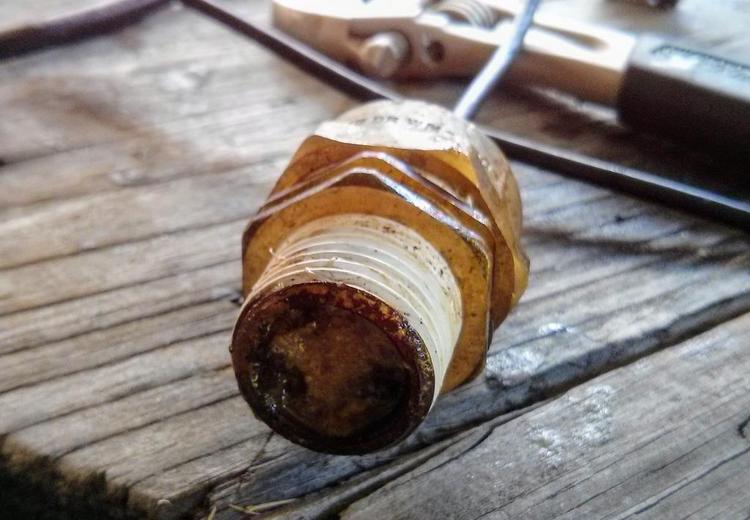
I decided to pull things apart and see what was going on.

The following photo shows the cause of all my issues. All that nasty built up gunk is hiding my temp probe, surprisingly beers have still been good even though they have been passing through this for I'm guessing a long while.

utFk6Wq.jpg


Anyway, after some reconfiguring my temp probe is now within the pot, I wish I did this the first time. It's reading with 0.1c of my thermopen. I also have fewer places for gunk to build up now.
 
I checked my setup last week as my beers have been a little bit on the sweet side lately and haven't attenuated as they should and found it to be 3 ° out. I put it down to an air pocket in the t piece, I done a caustic clean as well and it got a fair bit of gunk out. Got a beer fermenting at the moment so I'll see how that goes. It might be time for a strip down and a good soak but after seeing that photo.
 
malt junkie said:
On the hardware side there are a few things to check also. Obviously check your wiring of the circuit including the pump button. Without the element or pump plugged in, check the Pump SSR LED lights up when the pump turns on. (don't power the system with the enclosure open)

A picture of internal wiring would be very helpful.
Thanks malkjunkie, tested this - powered on, no element/pump connected. LED lights up fine.

The pump does work fine when in auto, LED lights up etc, I even restarted my 'auto' program after this issue and the pump worked fine! might be some config around running pump at a certain temp? Will look through the setup again. I remember setting pump off when boil, maybe there's another config somewhere.
 
zwitter said:
Hi brauduino builders

Wattage
Wattage. Equals volts multiplied by amps
So 2400 watts is 10 amps multiplied by 240volts
3600 watts is 15amps times 240volts
4800 watts is 20 amps times 240volts

Houses in most of Australia have a minimum of 2 power circuits. And neither may have more than 60% of the load in the house.

When we designed the controller the purpose of having 2 SSR and 2 inputs was so that we could run a second element on a different circuit.

My house has 4 power circuits. 2 in house and 1 in garage a nd the 40amp one for my welder.
I normally split my brewing across any 2 circuits. I have a 2400watt element and a chugger pump and that will happily run on 1 circuit. I use second circuit to run an over the side 2400watt element during boil. Chugger uses about 150 watts so one standard powerpoint can run single 2400 watt element and chugger etc.

I have a 50 litre pot but mainly do batches around 25 litres and 2400watt does a very poor boil. With the second 2400 watt i get a vigorous boil.

If 8 build another I would up the element to 3600 or 4800.

Figure 8 cable is just 2 wires attached next to each other and comes in lots of different sizes. The figure 8 i used was small and only for control signals to SSRs and to run the 12 volts. It was not big enough for the 240volt side of the SSRs.


Cheers

Zwitter
James

Sent from my iPad using Tapatalk HD
I've got 2 x 4500w camco elements in my 100L pot. Ramps at 1 deg every 30 seconds running them at 80% with about 80L - I like alot! Did notice the unit gets a bit warm, are fans mandatory running this much power?
 
buckerooni said:
I've got 2 x 4500w camco elements in my 100L pot. Ramps at 1 deg every 30 seconds running them at 80% with about 80L - I like alot! Did notice the unit gets a bit warm, are fans mandatory running this much power?
Fans will prolong the life of your SSRs. I could show you some photos of melted SSRs, though there was a dodgy batch or two of Foteks that did that, even under small loads. The heat sink without fan will deal well with around 3600w, above this and your risking over heating the SSR/s.
 

Latest posts

Back
Top