CraftBeerPI Brew Controller

Australia & New Zealand Homebrewing Forum

Help Support Australia & New Zealand Homebrewing Forum:

This site may earn a commission from merchant affiliate links, including eBay, Amazon, and others.
Im hoping someone may be able to help me troubleshoot my SSR. I have been getting my Craftbeerpi project going and have made good progress but run into a hurdle i cant figure out.

I have Craftbeerpi receiving temp correctly and have set the app and i can see it is tripping the SSR at the DC input side because a little Red LED lights up on the SSR. The problem is i don't get power at the plug where i have a small light 3 prong power load indicator plugged in.

I suspect this is due to not enough volts to set the SSR to turn on. I measure the DC input at 3.18v when the application is trying to turn on the load and the SSR LED is on. If i connect a 9v battery to the same input the SSR LED switches on and i also get full light as i should through to the power load indicator. Therefore, the SSR works but only with the 9volt battery to set it On. (The 9 volt battery is actually only providing 4.4v as it is a little flat).

I tried all i can think of. I use a 5.2v - 2.4amp iPad charger to power the RPI so think i have enough power into the RPI.

Anyway i can increase the volts to the SSR from the GPIO to get the SSR to trip.?

Thanks in advance.
 
I think you have correctly diagnosed the problem. I have played with a SSR and found that 3V is not enough for reliable turn-on. Use the rpi to switch a transistor and use a higher voltage on the SSR.
Dave
 
@dblunn
Thanks for the confirmation.

I don’t know anything about transistors and am new to electronics. Im just using logic and internet browsing to figure it all out so im trying to avoid circuitry if possible. Happy to read more but I had this idea… Is this feasible…

I connect a small 1.5v watch battery into my box and wire it directly to the SSR through an On/Off switch. I turn the switch On when I’m using the application. This provides an additional although small voltage direct to the SSR, then when I add it to the 3.1v from the GPIO when it is activated it will have enough cumulative volts to turn on the SSR but not enough when the GPIO is not activated. Would this fry my RPI GPIO because I am sending 1.5 v back to it via the DC side of the SSR and/or would it fry my SSR because it has 1.5v input which is not enough to activate it.…. Is this where a transistor comes in?

Before any of that though I am going to try a second SSR, it is exactly the same model but worth a try anyway. SSR model is Fotek 25DA, input is 3v to 32v.
 
tumi2 said:
@dblunn
Thanks for the confirmation.

I don’t know anything about transistors and am new to electronics. Im just using logic and internet browsing to figure it all out so im trying to avoid circuitry if possible. Happy to read more but I had this idea… Is this feasible…

I connect a small 1.5v watch battery into my box and wire it directly to the SSR through an On/Off switch. I turn the switch On when I’m using the application. This provides an additional although small voltage direct to the SSR, then when I add it to the 3.1v from the GPIO when it is activated it will have enough cumulative volts to turn on the SSR but not enough when the GPIO is not activated. Would this fry my RPI GPIO because I am sending 1.5 v back to it via the DC side of the SSR and/or would it fry my SSR because it has 1.5v input which is not enough to activate it.…. Is this where a transistor comes in?

Before any of that though I am going to try a second SSR, it is exactly the same model but worth a try anyway. SSR model is Fotek 25DA, input is 3v to 32v.
Try an Inkbird SSR, I'm betting your "Fotek" is one of the knock off ones and not within spec
 
Hi mate,
Sounds like a dodgy solution to me, you are better off using 12 V through a transistor and limiting the current through a 470 Ohm resistor (you want about 20mA through the SSR). I have attached an equally dodgy image that may help.
Regards, Dave

Trx.JPG
 
Im running a fotek nock off and have no issues with the 3 v. As long as the light is coming on it should be active. Have you got a photo of how you have it wired up?
 
[SIZE=10.5pt]Thanks for your help guys. First time ive attached in the forum and trying to share form Google drive so i hope you can see this....[/SIZE]

[SIZE=10.5pt]The images show my wiring. In the green light image, the green light On is what is expected when SSR flow is Off. When SSR flow is On it should have Red light also. This does not happen when controlled via the RPI GPIO but does work when i connect a 9v directly to the DC inputs of the SSR with GPIO disconnected.[/SIZE]

I think the transistor is the way to go but have to wait 4 weeks for ebay delivery from China. @dblun, thanks for the diagram. I think o get the setup but was hoping to use a 9v battery as the second power source as i will have one in the project box already.

See images here
 
cant really see much from those pics. have you got the ssr gpio2? make sure in software you have the correct gpio pin selected for the heating element.

Also try plugging a lamp into it.
 
I am only running 1 * SSR as I currently BIAB with gas but I plan on switching to electricity and an urn which is what im getting this setup for.

In the software i setup the Kettle with GPIO 26. I use this Pin on the RPI to drive the DC side of the SSR. Im sure it is correct because i can see the Red light on the SSR come on and off in line with the auto kettle toggling on the application.

Im going to try and rewire using less joins and solders in case i am loosing volts and current in my dodgy wiring. Im also going to switch to a computer PSU to supply 240v, 12v and 5 volts all at once. That way i can hook up a transistor if i cant get this SSR flowing.
 
Hi, yes you can use a 9V battery, just drop the value of the series resistor to 330 Ohm.
Dave
 
tumi2 said:
I am only running 1 * SSR as I currently BIAB with gas but I plan on switching to electricity and an urn which is what im getting this setup for.

In the software i setup the Kettle with GPIO 26. I use this Pin on the RPI to drive the DC side of the SSR. Im sure it is correct because i can see the Red light on the SSR come on and off in line with the auto kettle toggling on the application.

Im going to try and rewire using less joins and solders in case i am loosing volts and current in my dodgy wiring. Im also going to switch to a computer PSU to supply 240v, 12v and 5 volts all at once. That way i can hook up a transistor if i cant get this SSR flowing.
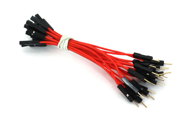
yeah i have mine connected straight to the Pi via header leads
qStvW.jpg
 
Still no go after a rewire but i have tested again and am convinced the SSR does not have enough volts to switch on. It definitely turns on my heater when connected to a 9v battery. The 3.2v from the rpi is just not quite enough to activate the SSR even though the specs say 3v to 32v input. I have ordered an Inkbird one and some transistors. Its a 4 week wait for delivery.....
 
tumi2 said:
Still no go after a rewire but i have tested again and am convinced the SSR does not have enough volts to switch on. It definitely turns on my heater when connected to a 9v battery. The 3.2v from the rpi is just not quite enough to activate the SSR even though the specs say 3v to 32v input. I have ordered an Inkbird one and some transistors. Its a 4 week wait for delivery.....
Hi tumi2,

Can I make a suggestion that you've probably already tried? I'm at the same stage as you and have just wired up my prototype and also found the pi wouldn't activate the SSR (also using a dodgy ebay Fotek). A 9V battery did however. I was annoyed thinking I was having the same problem as you, but I played around with the craftbeerpi dashboard anyway. On the panel that has your kettle (or any other hardware) there is a little button that looks like a flame. When I hit that, it worked. I can now toggle the switch on and off using that, suggesting the SSR is getting enough love from the pi.

Now that I've figured that out, I can't seem to get the SSR to fire when I hit 'Start" on the "steps" panel. I assumed once all the steps were set up, you just hit start and it ran from there. Watching the youtube video, I see he hit a heap of little buttons on the kettle panel, but I don't actually know what they're all for.

Can anyone give me an idiots guide to actually getting it to run the mash steps?
 
The four buttons he's playing with on the video are a diamond shape, a car, a flame, and a refresh logo. What are the first 2 for (as far as I can tell the flame just manually turns it on) and I'm guessig the last one just refreshes it.

Ok, so the first one (diamond) sets target temp, but isn't the temp already set in the mash schedule?

Edit: Ignore all that, I just figured it out (I really should apply some restraint before being a pest poster). When you hit the car button it runs the mash program and activates the SSR. The diamond is to manually set a temp (to override the mash sched I assume).

It's all working well. Such a cool project!
 
Hi MatB, unfortunately my issue is not as you describe as i have the software working fine and it does toggle the SSR with the AUTO setting on the app. My problem is that when it toggles the SSR lights comes on but only dimmly and is not enough to switch On the SSR. I have ordered new SSR and am reading about using a transistor as the previous poster suggested. Glad to hear yours is running.
 
Tumi2 does your SSR work with a different power source? A 9 volts block battery can be used to test the device.
 
@alexbrand - yes it does with with a 9v battery.

An update - i got this working over the weekend using a transistor to increase voltage slightly. I am using the 5v power rail of the PRI as the extra power source. I run the 5v from the RPI to the positive side of the SSR, the negative side of the SSR to the Collector pin of the transistor. I run the GPIO kettle output (in my case GPIO26) through a 330 Ohms resistor into the Base pin of the transistor. I connect the Emitter pin of the transistor to the Negative rail of the breadboard on the same side that i earth the 5v from the RPI.

It work instantly after doing this.

I am now trying to better work out what resistors i need. Some say i dont need one between the 5v input and the Collector pin, other say i do and im not 100% certain about the resistor between the GPIO data and the Base.

Anyway, as @dblunn suggested it seems have a dodgy Fotek SSR that is slightly under specs and requires more than 3v to activate it.

Thanks to everyones assistance with this.
 
Great to hear that it is working now.
Seems like some SSRs do not meet their own specs (input voltage).

I am about to switch from my old brew controller to BrewPi, too.
 
Today I used the craftbeerpi controller to do a brew for the first time. I couldn't get the mash schedule recipe to actually control the kettle. I only have one kettle (BIAB) and no pumps/agitators etc. It reads temp ok, and i can manually activate the element using the flame button on the kettle panel. When I wanted to start the recipe schedule, I opened my recipe, hit the little car button on the kettle panel and pressed start above my recipe schedule. It wouldn't activate the kettle until I hit the flame button, and then once it reached temp it would just keep climbing. Also the timer clock that appears underneath each step would just stay at 00:00:00 and not move. If I hit start again, it would just skip the step. Somehow I managed to get one of the steps to work (but the timer wouldn't), and it would automatically use the overshoot logic to shut off close to target temp, but then it would just fall and not reactivate.

I ended up just turning the kettle on and off manually to control the temp. Not what I had planned.

What the hell am I doing wrong? All I want is for it to activate the kettle element, maintain temp then move on to the next step according to the times and temps I've preset. I'm hoping someone smarter than me can see where I've missed something. I set everything up following the official youtube clip.

Cheers! B)
 
Back
Top