CraftBeerPI Brew Controller

Australia & New Zealand Homebrewing Forum

Help Support Australia & New Zealand Homebrewing Forum:

This site may earn a commission from merchant affiliate links, including eBay, Amazon, and others.
terragady said:
Can't you just install it from scratch again? 2.2 doesnt not meant to be for brewing yet, just for development from what he says.
yep i could but i figured there may be only minor changes that might be easier to upgrade.
It is not ready for brewing but the bulk of it works well and is a large improvement on v2.1.
 
Hoping for some thoughts about wiring multiple DS18B20 temp sensors to the RPI.

I currently run 2 temp sensors using separate GPIO and a dedicated 4.7k resistor for each sensor. It all works fine in CBPI v2.2, i can see each sensor in the hardware list, i can switch SSR's with both sensors and can record separate temparatures.

However, after doing some reading i understand that i have this design incorre t and that i should actually chain the sensors through a single 4.7k resistor. Furthermore they should all share the same GPIO 4.

What is the reason for chaining the sensors and can i just keep my current setup? Is it just to save curcuitry and the fact that the RPI GPIO 4 can accommodate multiple sensors or is there a technical reason why i must chain them.?
 
tumi2 said:
What is the reason for chaining the sensors and can i just keep my current setup? Is it just to save curcuitry and the fact that the RPI GPIO 4 can accommodate multiple sensors or is there a technical reason why i must chain them.?
The idea of one wire was to use less IO and run more devices.

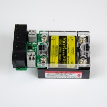
brewpi_onewire_ssr_expansion_board_3.jpg

this little doodad is a one wire interface(using RJ12 sockets {telephone jacks} for the one wire cabling) for an SSR it has a second out put for a second SSR and three further jacks for other one wire devices eg. temp probes. this sort of thing really tidies up your wiring too.

Cheers
Mike
 
That is a really nice device. E-bay ?

You would laugh at my wiring. I run 3 * SSR's and 2 * temp probes and everything through a breadboard so it is a bit like spaghetti. It is housed in a HP Desktop stripped out.

It does work though and color coding helps a lot.
 
Your not in a bad spot in Sydney plenty of fellow brewers into their electronics. Once you get the circuitry and a lot of it is simple, especially one wire, you can make a custom board with things set out the way you want. The pic above is from the brewPI store they've got onewire boards for motorised valves too.
So in essence you could have coming from your controller
  1. one cable for all your sensors, one for all your pumps and valves, and another for all your heating or
  2. one cable for each vessel, controlling all of the above
  3. one cable for the entire rig, controlling all of the above
It's simple bus topology, the down side is; the longer the bus the harder it can be to track faults. So I would choose either option 1 or 2 probably leaning heavily toward 2 though.

BTW if it aint broke......
 
malt junkie said:
The idea of one wire was to use less IO and run more devices.

brewpi_onewire_ssr_expansion_board_3.jpg

this little doodad is a one wire interface(using RJ12 sockets {telephone jacks} for the one wire cabling) for an SSR it has a second out put for a second SSR and three further jacks for other one wire devices eg. temp probes. this sort of thing really tidies up your wiring too.

Cheers
Mike
Wait is not it that 1-Wire protocol can use only 1 GPIO at the time without kernel modifications? and by default this gpio is 4?

@tumi2
how were you able to connect more sensors to different GPIOs?
 
arduino set what every pin you like(within reason) and multiple buses is doable(the default is GPIO 4?), I haven't played with the RPI GPIO (yet).
 
wait, but what arduino is doing there? :) There is only RPi, no arduino. I know that in arduino you can use multiple GPIOs but not in RPi. Default for 1Wire is GPIO4 and this can be changed easily, but if you want multiple sensors connected to multiple GPIOs then this is heavy stuff which include modifying and compiling the kernel.
That is why I am surprised how he get it to work when connected 2 sensors to 2 GPIOs :)
 
Really sorry for the confusion....

i just traced my spaghetti wiring and realised that i DO share GPIO 4 across both sensors but i use separate power, earth and resistor.

Needless to say i am going to clean it up this week and use single circut for all sensors.

Appoligise again....
 
Anyone got any pics of their setups yet?
I'm looking for some inspiration for my build
 
I'm hoping to have something (most likely ugly) soon, honest!
sp0rk said:
Anyone got any pics of their setups yet?
I'm looking for some inspiration for my build
 
sp0rk said:
Anyone got any pics of their setups yet?
I'm looking for some inspiration for my build
Is this the sort of thing you're after?

IMG_1557.JPG

(you might notice some ****** MS Paint stuff where, to avoid confusion, I've blotted out some power cords that were coiled underneath the box).

It looks a bit of a mess, but once I close it up it's nice and easy to handle.

Inside is a RPi 3 and Sainsmart 4 switch relay.

Clockwise from the bottom left is the power cord to mains and the power source for the RPi, then 2 temp sensors. Then on top I have 3 sockets for 3 of the 4 relays (I could buy another socket, but at the moment I really only need 2 (one for cooling and another for heating).
 
No that's good
For some reason in my head I was over complicating it looking at other people's rigs with breakers built in, etc etc
I'm going to have 2 x 10A leads going in, 3 leads coming out
1 out will be for my HLT, which has a 2200w element, so I have 200w left for the Pi to come from the same in
The other 2 out will be my hex, which is 1800w, and a keg king pump, which is something like 60w
 
kaiserben said:
Is this the sort of thing you're after?

attachicon.gif
IMG_1557.JPG

(you might notice some ****** MS Paint stuff where, to avoid confusion, I've blotted out some power cords that were coiled underneath the box).

It looks a bit of a mess, but once I close it up it's nice and easy to handle.

Inside is a RPi 3 and Sainsmart 4 switch relay.

Clockwise from the bottom left is the power cord to mains and the power source for the RPi, then 2 temp sensors. Then on top I have 3 sockets for 3 of the 4 relays (I could buy another socket, but at the moment I really only need 2 (one for cooling and another for heating).
I wouldnt trust those Sainsmart relays at 10A, ive blown up two units at well under 10A on other projects. They can handle limited 10A peaks, but sustained 10A for things like elements and they start to get quite toasty.
 
Hey guys I've just made the switch to CBP after using StrangeBrew Elsinore for the last year or so.

I have 12v pumps hooked up to sainsmart relays and I need to invert the gpio signal for just those devices.

Has anyone done this - I know it's an edit to the python code somewhere, but I can't find where.

Cheers!
 
sp0rk said:
Anyone got any pics of their setups yet?
I'm looking for some inspiration for my build
Here is a Google Drive link to my images. Its a bit hard to make much from it. Hope it helps though.....

The entire build is in a old HP Small Form Factor box. It has 3 * Inkbird SSR's, 3 * GPO plugs that i connect my Recirc pumps, Kettle Heating Element, Sparge heat element into. The SSR's sit on large heat sinks which take up a fair bit of space.

I connect 3 * 1 wire temp sensors through old school Serial plugs. The good thing about this is that i can run 2 or even 3 separate temp probes from a single 9 pin serial plug.

I do it all through a breadboard which makes playing and troubleshooting easy and so far i have not had any issue with loose connections on the breadboard.

The computer sits in a shelf in my brewery trolley which is built on a strong flat bed trolley so the entire brewery is mobile.
 
Brilliant, that's more or less exactly what I was thinking mine would look like
I would guess a lot of the builds I'm seeing online are building in sub boards for the power or something

Thanks!
 

Latest posts

Back
Top