I have a PCB for this project made from the drawings and I'll build it up over the next couple of months.
There a number of things I like to ask about,
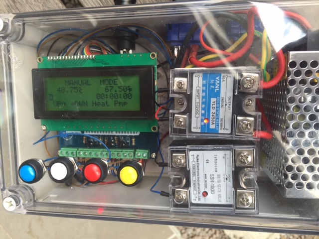
What's the best way to mount it all in a enclosure/box?
Are there any pictures?
The small display, do I just cut a matching hole in the enclosure and push the LCD into it?
There seem to be two possible sets of buttons a matrix membrane and real buttons.
How would I mount the matrix membrane so I could press its keys?
Or
If I use real buttons how do I connect them to the arduino?
Many thanks. Aamcle
There a number of things I like to ask about,
What's the best way to mount it all in a enclosure/box?
Are there any pictures?
The small display, do I just cut a matching hole in the enclosure and push the LCD into it?
There seem to be two possible sets of buttons a matrix membrane and real buttons.
How would I mount the matrix membrane so I could press its keys?
Or
If I use real buttons how do I connect them to the arduino?
Many thanks. Aamcle
")