Water Level Sensors

Australia & New Zealand Homebrewing Forum

Help Support Australia & New Zealand Homebrewing Forum:

This site may earn a commission from merchant affiliate links, including eBay, Amazon, and others.
Through calibration, I know how long to switch the solenoid on to get the volume I want. It is part of how I get my system to autostart whilst I am still sleeping or otherwise occupied;

http://www.aussiehomebrewer.com/forum/inde...st&p=433700

It is also possible to manually fill the HLT the night before with only the volume of water needed for dough in and empty that at a preset time. This is the technique I am trialling on the weekend;

One timer to start the mill motor and open the solenoid and turn it off some time later and another to start the mash cycle (pump and heat exchanger)

going a little OT;
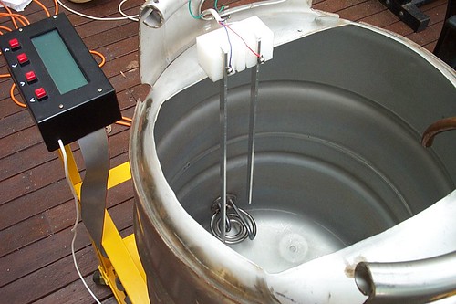
The system ramps and soaks from 20degC to mash out using the heat exchanger, so there is no great importance on strike or sparge water temperature for me. My heat exchanger is quite efficient at changing mash temperatures and really negates the need for a HLT.

I don't see a problem with the mash returning to 60-70 deg during sparge and then recirculating to mash out temperature. The enzymes should be mostly denatured during the first mash out.
 
I just ran some numbers. Unless there is something wrong with my calca, the pressure in the tube is too small to measure with a cheap pressure sensor for rather normal sized kettles/HLTs (approx 50 - 100cm deep). Which of course explains why I haven't seen a liquid level gauge like this before.... <_<

However if you put a piece of styrofoam (the float) at the bottom of the tank connected to the plunger on a syringe-like deal then you could kind of amplify the pressure and be able to use a standard pressure sensor to measure liquid level. The float doesn't have to be styrofoam - it could be an air filled copper or SS tube.

Just found this which references the motorola pressure sensor from Jaycar.
 
You wont find a cheap sensor - liquid level measurement is done in numerous ways - all quite expensive:

I was hoping that wasn't the case! :)

I always thought that if I ever got round to building a brewery worthy of automating that I would use these - the automation side of level control in a 50L brewery is usually to fill up a vessel to a pre determined level then heat it. The analog reading of how much in the tank is immaterial - repeatability is paramount.

Although I'd like to fill to a certain level in the HLT, and then empty certain varying volumes into the mashtun, so a reading of how much was in the tank is essential...
 
Hey guys,
This is what i found when trying various ways of measuring liquid levels in my system.

-Differential pressure sensors worked ok but had a lot of trouble with liquid getting into them and also at 50L you need a very sensitive sensor i think mine were mpx100 sensors which if i recall correctly they went to around 1psi, any variance in the temp of the water used to play havoc with these sensors also if you got a small amount of liquid in the air line the surface pressure of the water would hold pressure in the line and give false readings.

- Load Cell or scales are the way to go, search eBay for industrial scales with rs232, they can be had for around $200. These will give you an accurate measurement regardless of liquid temp , viscosity and resistance.

- Resistive. If you are doing the same size batch I would recommend this type. I use it in my 50L system. I have a stainless rod suspended from the top of the tank for high level and a insulated bolt in the bottom of each tank to show empty. These are wired to my USB IO controller and just register on or off, very stable and simple.

Cheers.
Jono
 
Can you fill the HLT, cut off the water source when the float kicks in then empty based on timings assuming you will have a consistent flow rate out of the tap at the bottom?.
 
Can you fill the HLT, cut off the water source when the float kicks in then empty based on timings assuming you will have a consistent flow rate out of the tap at the bottom?.

I could, although a consistent flow rate would (I assume) require the valve fully open, which is fine for initially filling the mash tun, but not so good for sparging. For sparging I'd want to throttle back the flow.
 
I was hoping that wasn't the case! :)


Although I'd like to fill to a certain level in the HLT, and then empty certain varying volumes into the mashtun, so a reading of how much was in the tank is essential...

Well - given that the head pressure wont change much - you should be able to do this based on time.

Fill to 50L - easy to replicate this using a 'cheap' float. Then based on a valve opening - which will have a fixed orofice and hence backpressure - will give you a fixed volume per minute/second open (within reason). Imperically you should be able to fine tune this to be quite accurate - especially if you use gravity as opposed a March Pump :ph34r: and the same hoses each time.

Johnathon is right - a gravometric based system would be very accurate - I still think given your earlier comment - that a switch and a valve and a timer are going to be easier to customise than trying to control based on a signal from a load cell. Bearing in mind unless you buy a head unit for the weight reading - therefore giving you the ability to tare and set inputs to your automation system based on weight setpoints - you are going to have to do some work at the component level to get this all going.

Level Switch/Timer/Valve - you wont get cheaper.

RM
 
In terms of instrumentation this would be dead easy, but it would require another container.....

For automated filling of the HLT or mash tun, why not have a fill grant, similar to the outflow grant usually present between the mash tun and kettle in many commercial breweries? Make this fill grant about 1.5l in volume with a decent accuracy float switch or resistive float sensor at the 1l mark. Fill from the bottom until 1l is in the grant, then open a drain valve to dump the contents into the HLT/mash tun. Repeat x times to get x litres in the vessel.

It's a little more involved piping-wise but it's dead easy and very cheap.
 
Without reading the whole post so forgive me if its been said.................

Ultrasonic level sensor in a strait sided vessel with a 4-20mA output to a display is what i plan when i can get my hands on one.

Span your range.... say for eg. 0 - 600mm to 0 - 50 liters.

easy.

Edit...... just had a think and this will be a bitch in my HLT with HERMS coils, temp probes and heat elements ect to provide false echos but in a vessel with clear view to the bottom......... perfect!
 
what I had in mind was simple. When the water reaches the probe it pulls a small relay in which shuts your solenoid valve down. HLT is to the desired level probe can be adjusted up or down to suit. Regarding varying levels in MLT after looking at flow meters and some pretty expensive gear I settled for timing circuits to shut water flow off as well as gas. This idea was take from irrigation setups. I am working on this at the moment. I will draw up a circuit diagram of the former idea and post it here and if you are looking for a cheap timing device other than commercial irrigation ones I see in Jaycars cattle dog which I just received last week a little Micro driven timer which you could sub switches rather than jumpers to get different timing combinations Cat No. KC-5464 also see they have a water level sensor for eight bucks, circuit board with works would save cobbling my idea up on a tag strip. The output would probably power up a small minature relay to control your solenoid valve.
I even see a project there for a computer interface. Things are moving ahead with Jaycar.


Cheers
 
Sorry to go so low-tech, but I cooked up something like this a while back for a film processor's bleach dump overflow jerry can.

If it's for attended operation, get a couple of pieces of threaded SS rod and matching nuts. Mount either on a piece of SS bracket (with grommets to isolate the 'probes') or plexiglass / nylon / teflon / etc or through the non-conductive lid of the container. Two holes, threaded rod through and bolted into position. One higher than the other by say 20 mm. Tighten nuts. Affix terminals (or drill through the rod and wrap wires and use heat shrink tube for a nicer finish. Put a 9V battery and a small piezo siren in series (polarised) on one terminal and the other terminal returning to the 9V battery. The little piezo siren is annoyingly loud. Louder siren? Probably 12VDC, so use a plug pack instead of a battery.

You can use the same arrangement without the siren and power it from a PLC and digital I/O card (used Siemens ones with software kit for making your own firmware go for a couple of hundred bucks these days, other kinds are around; old and slow is OK as this isn't a high speed process). If no software comes with it, then use your Google-fu to find something liek a back up copy somewhere :) . The I/O on these is usually 24VDC. In software, it's like Port goes high then [other things happen]. Not overly hard. The development kit is a bit of a brain bender at first, but you can wrap your head around it after a few hours.

Cheers - Fermented.
 
Try Here for ideas.
The control unit is about US$40.00. Was looking at doing something similar before I changed to HERMS.
Cheers
Sully
 
Like Roger Mellie I work with these things for a living. Ultrasonic sensors and flow meters at the cheaper end would be the least reliable in my experience, mass is going to be the most reliable. But for the idea of a tube filling from the bottom and measuring the sealed in pressure, the more conventional way to operate it is as a bubbler ie 1) have a tube as described venting to the base of the vessel, 2) fill vessel with water, 3) with a hand pump or compressor pressurise the TOP of the tube, 3) reduce the air input until the tube is only slowly bubbling (tube is empty of water but no friction loss from air pumping and 4) have a pressure sensor in the tube with the appropriate range to measure exactly the height of water it is pushing against.
 
I got my design from when I was running a job installing a water bottling line at Coke a few years back.

They have the resorces (Money) for all maner of fancy level transmitters that tell them exactly where the level in the vessel is. They use pressure, ultrsonic and capacitive systems for their analogue systems.

The bit that supprised me was that their fail safe systems were simple and cheap sensors. The relay costs under $100 and the probes are stainless set-screws taped into a plastic bung that is in turn screwed into a standard stainless socket welded into the vessel. Another "earth" stud is welded to the vessel.

This system works every time and can be set up fail safe for high or low level aplications or the relays I use can be used with three probes (one is the earth refrence) to cycle a pump or valve to keep the level between two points. This is perfect for control of the sparge valve when fly sparging.

Derrick
 
Water and wort are excellent conductors. For my mind the conductance probe method is by far the most reliable and the cheapest too.

For my brewing I don't really need infinitely variable measurement down to the ml or even hundreds of ml. Strike and sparge volumes may need to vary a couple of litres tops around pre determined points.

1567151585_cb094aff50.jpg


Most micro controllers have multiplexers in front of the ADC so it is trivial to cut a range of probe lengths and hook them up. As you can see in the above I used a small plastic block with slots cut for 5 probes, but only ended up using 2. A single screw hold the probe so they are very easy to adjust.

I was actually thinking I would mark or notch the probes so that they didn't need to be clamped by the screw. I would then be able to tweak the desired levels accurately by hand when I loaded the grain. Just like reading a ruler. Actually that would probably we easier than keying in desired values via the controller. The only downside is that the exact values used would have to be recorded by hand.

The circuit is dead simple. Just connect the vessel to gnd and the probes pretty much straight to the ADC input on the micro. The Atmega has programmable pull up resistors so just turn them on in software. Sample the ADC and apply a simple threshold when you want to know the water levels. Too easy. From memory the resistance was about 20K ohm through water for reference.

I had non brewer mate who saw my setup and said "beauty you can do an automated system to top up my pool from my rain water tank". Same principle, just difference probe implementation. Works well despite the much harsher environment.

I also use a single probe in the kettle to ensure I never apply power to the elements without them being covered.

792492714_95a55d1c0a.jpg


You can see I prototyped the probes with a rustic looking bit of wood with some holes in it for the probes:

638767118_0b7449106e.jpg


Haha.... looking through my photo stream I see a couple of AHBers tries to demonstrate what they though was an effective "probe" system at a qld swap... dodgy bastards....

1872575057_cff8cd3e00.jpg
 
ultrasonics are actually danm cheap to use. in fact you could probably get away with a standard 40khz transducer, an AVR or PIC and a few hours if you're handy that way.


Alternatively it may be possible to use capacitive sensing, although I have heard the metal of the keg can interfere. I am sure there are ways around it though. Capacitance sensing is danm sensetive too if you need it to be, I was able to accuratly sense a fly buzzing on one side of a room ;)
 
Using laser isnt a bad idea - same way you make those long-range laser mics using modulation of the laser on a surface like glass.


Actually to take it a step further, I've read a report about some guys who managed to sense the cpu working (residual EMF) and managed to actually determine individual commands being executed on a remote CPU.


:D

</offtopic>
 
Back
Top