Tight Arse Stir Plate

Australia & New Zealand Homebrewing Forum

Help Support Australia & New Zealand Homebrewing Forum:

This site may earn a commission from merchant affiliate links, including eBay, Amazon, and others.
I'm slightly confused and can't find an answer amongst this mass of pages.

This guide says to use a 500ohm linear pot from Jaycar. Is this the right one?

http://www.jaycar.co.nz/productView.asp?ID=RP3502

I'm confused about the wattage. All the American guides suggest a 3w pot is needed. This one from Jaycar is only 0.5w.

I'm using a 12v power supply and a 12v fan that pulls around 150 mha.

Will that pot from Jaycar work?

Thanks.
 
The minimum you would need is 1.8 watts.
P=V*I
P=12*0.15
P=1.8 watts
So 3 or 5 watt would be the go
 
Ok thanks.

Seems to be very hard to find a 3w one in New Zealand at a reasonable price.

Are there other options that are real cheap?
 
shmang said:
The minimum you would need is 1.8 watts.
P=V*I
P=12*0.15
P=1.8 watts
So 3 or 5 watt would be the go
False.

This is the power dissipation of the fan, not the pot. You're right that P=VI. But this is different for each component, as the voltage drop across each will be different, and there won't ever be a 12V drop across the pot.

Very basically (slightly wrong, due to the complex nature of electric motors under load, but close enough for a basic approximation):

at 12V, the fan draws 150mW. This makes the armature resistance 960Ω. We then have our pot, which is 0 - 500Ω. We can assume a constant 12V across both resistors (Rp and Ra). Current can then be determined for any Rp (pot resistance). Pp = I²Rp. I did a plot of this, and came up with a max value of 0.0338W < 0.5W

This is all assuming that the maximum power dissipation (as quoted 150mW) occurs at maximum power, and not at stall. If the measurements are taken at different points, the calculations will vary. If you could put a multimeter across the fan while it is unplugged, I can update those calcs and give you a better response.
 
I know I've been gone for a while, but I thought we'd cleared this up a long time ago. Do not use a pot. Use a variable regulator or a pwm (switchmode) fan controller. There have been several circuits posted in this thread, including one of my own.
 
It probably has been covered, but you can forgive someone for not reading through 40-odd pages. I posted incomplete specs for my design on the previous page. I've updated them (filled in the blanks, everything is a little neater now), and produced a new board layout - one optimised for a Veroboard or similar. Same components, etc, and all available at Jaycar.

PWM Schem.png
Parts:

2 x 1kΩ resistors (RR-0572) $0.46
1 x 100kΩ linear 9mm pot (RP-8518) $2.75
1 x 1N4004 Diode (ZR-1004) $0.50
3 x 0.01μF Ceramic Caps (RC-5348) $0.64
1 x STP16NE06 mosfet (ZT-2277) $2.45
1 x NE555 timer (ZL-3555) $1.25
Plus a 1" x 2" piece of 'veroboard' style prototyping board, and whatever connectors/bling you feel necessary. I found that putting a polarised fan header on the board (pictured) with mating connector on the fan to be very handy. You could always do that with the power too, but I just soldered mine in.

PWM Board.png
Veroboard Layout. Dark blue lines are active lines / signals that we want. Red lines are wire bridges that we need to add to the board. Cyan lines are verobard traces that must be cut. You do not need to remove the entire length - as long as electrical contact is broken. I usually just use a stanley knife to cut a clear (2mm or so) break.
 
Yeah sorry for not reading every page, I tried but got confused.

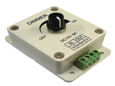
Anyway, I did get the feeling that a pot is no good so I have just bought an LED dimmer. Sorry for bringing up an old topic.
 
I'm glad you brought up this old thread, made me realise I already have all the parts to build one!
 
My stirplate died some time after I went to bed last night and after some tinkering this morning I found that the PC fan controller (just a pot) must have crapped out :(
Luckily i'm using a variable power supply so I can vary the voltage that way, but I might have to make a new controller going off MCHammo's plans some time this week

Also decided to throw out my old stir bar this morning and try out my new 30mm one from Wiltronics
Very happy with it, it take much higher speeds for it to fling off than the old one did :D
 
I've just knocked my stir plate together using the link provided by Zwickel as a guide. Four bolts and a scrap of perspex and it's done. I think it's a pretty elegant design.

From my collection of orphaned chargers, I found one with variable output which gives me as much control as I need, so no need for pots etc.

6V will produce a good vortex in 2 litres, 4.5V is good for 1 litre and 3V in 100 mL is plenty. 9V in the larger volumes produces a full depth vortex with lots of bubbles being ejected up the sides of the flask. This might be a good setting to use for 10 minutes before adding the yeast to get some oxygen into solution. 12V just throws the bar.

stir plate.jpg

vortex.jpg
 
I finally got my stir plate together today. It's not pretty (I can't solder for ****) but I'm happy with it.

My experiences:
I initially purchased a PVM LED dimmer like this one
dimmerV1.gif

But I was unhappy with it as it caused the computer fan I was using to emit a constant whine as the pulses were sent to the fan at low speed.

With my limited electronics knowledge I removed the control knob inside (potentiometer) and twisted the wires together for a quick circuit. My 9V 200mA AC adaptor made short work of frying the potentiometer so I figured more research was required.

Lethal Corpse seemed to know what he was on about, and others had followed his recommendations with success so I collected the necessary parts, and a cheap soldering iron ($13) from Jaycar and sat down to it.

LethalCorpse said:
updated diagram to make it a bit neater and include the new values.
Jaycar parts:
LM317T - ZV1615
5k linear pot - RP3508 or RP7508
knob to suit - pick one. Not the ones which say "spline" or suit 9mm pot
680ohm resistor - RR0568
switch - pick one. Any will do, so long as it's a latching type, not momentary. Pushbuttons, toggle switches, rockers, etc.
10u cap - RE6070
100n cap - RC5360
Perhaps 2 hours later (did I mention I can't solder very well?) I was done. I haven't mounted it yet, but the circuitry works, and from my experiments with the LED dimmer I know that the fan doesn't need to spin very fast, and that the width of the magnets, and proximity to your vessel and hence your stir bar, are very important.

I bought this 30x16mm stir bar (http://www.ssapl.com.au/store/001630.html)%C2 Science Supply Australia in Mitcham. The guy on the phone was reluctant to sell me just one, so whilst I wanted to push him to ask if it could be posted, I settled for making a trip out there.
It seems to be a good size, although the jar I am using has a convex base which makes for an unstable stir bar as the speed increases.

I purchased round 8x5mm rare earth (neodymium) magnets which seem to do the job, but I might upgrade to something bigger as they're only just coping. Stacking them on top of each other gives a stronger field, but at the expense of having to mount the fan lower which isn't ideal. Does anyone know if mounting them side by side will be effective? They definitely won't sit like that by themselves, but I figure I could glue them down it'll work.
 
I started with a PC fan and when I upgraded to a PWM power supply circuit and more powerful magnets, found it wasn't working as well as expected. Had a thought the magnetic field of the magnets may be messing with the current in the PC fan (which constantly goes on and off due to the PWM supply) so made a change as shown and works really well now.


68-030114184525.jpeg
 
Nice work malty,

You're right, mounting strong magnets directly onto PC fans can render them temporarily useless. They use an internal magnetic sensor (hall effect sensor) to know when to power the different electromagnets to make it spin. Adding a strong external magnetic field can trick the fan into thinking it isn't spinning.

We currently get around this by adding some metal behind the magnets to shunt the magnetic field before it interferes with the motor, but your solution of separating them is great too so long as you can keep it balanced.

Looking good!
 
Thanks ... interesting about the use of hall effect sensor in the PC fans. I have stuck the magnets onto a strip of galvanised steel to keep the magnetic field away from the fan side but it didn't seem to quite do it.
 
Necro this tiger.

A couple of questions for those in the know:

1. Does this need a nice neat vortex? Mine is flinging around the stir bar in my 500ml Erlenmeyer. If if does ;

2. What causes the flinging stir bar? Speed, position on stir plate, magnet position, crappy stir bars?
 
1. Not really, just needs to keep moving so that the yeast stay suspended and (assumption here) to provide continued O2 uptake at the surface.

2. Either not enough hold from the magnets (too far away or not strong enough), or more likely magnet position.

The magnets need to hold the bar very well centred on the centre of rotation, otherwise it will throw the bar when the speed is high enough.

Same thing happened to mine after one of the magnets broke loose, didn't glue it back in exactly the right position and I can't get it near full speed.

Timely reminder to fix it before I need it again (I've got two, so I keep stalling!)
 
(only read latest posts so prob just repeating here) - Place the magnets on the stir bar when you set them in the epoxy.
When I made mine I took care when setting the magnets in the epoxy. I placed the stir bar on the magnets so that they set as they want to. Eg. You can fight with magnets, They have poles etc. Just play with them a little. If they aren't comfortable with each other with the stir bar then it maybe hit and miss to work well.
 
Back
Top