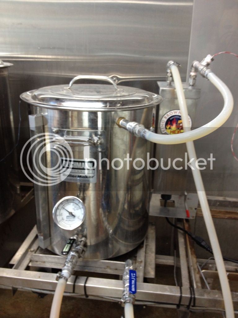
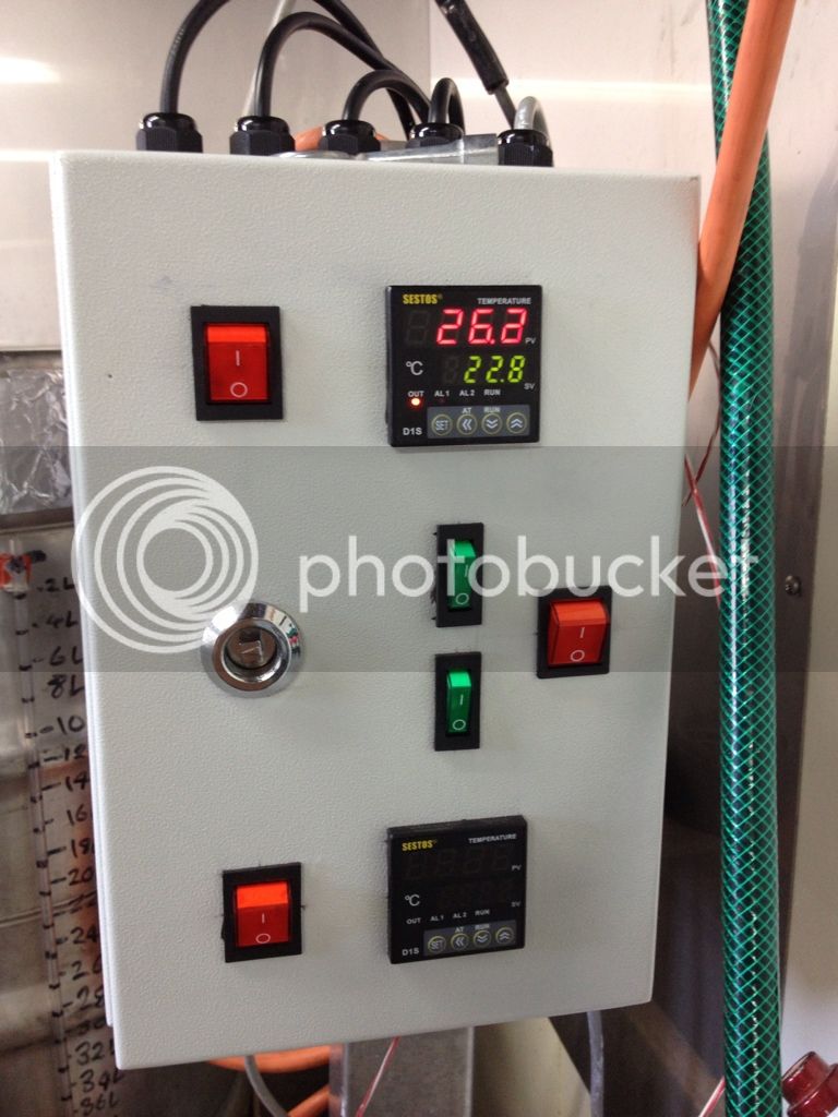
Pid Newbie Stuff

Australia & New Zealand Homebrewing Forum

Help Support Australia & New Zealand Homebrewing Forum:

This site may earn a commission from merchant affiliate links, including eBay, Amazon, and others.
A question...
If you use a pt100 sensor there are 3 wires, but only 2 spots to attach them on the PID.
Which ones go where?
Mine isn't registering as receiving a clear temp signal, and yes that PID is compatible with rtd pt 100.


What brand/model PID is it, there must be a third hook up somewhere?

QldKev
 
Legend...

Thanks yet again Kev.
 
Does it matter what side of the led the resistor goes to?

Does it matter which 12v wire goes to which side of the led?
 
Does it matter what side of the led the resistor goes to?

Does it matter which 12v wire goes to which side of the led?

The LED does need to be wired for polarity.
The long leg of the LED is POS, attach the resistor to it, then hook it up to the pos line.
Connect the short negative leg of the LED to the neg run.

The resistor does not need to be wired for polarity, so as long as it's inline it doesn't matter which direction it's pointing.

Technically you could run the resistor after the LED as long as you got the LED's polarity correct, but I prefer to wire all resister before as a standard so it's easy to see whats happening.

edit: Just so you understand, the LED wiring doesn't have to be in the middle of the run, you could jumper into the screw terminals at either the PID or SSR

QldKev
 
Awesome, thanks Kev, i understand completely.

Will go get led and resistor Monday while i'm waiting for the rest of my parts.

Cheers again for your help getting this project off the ground. I love learning all this stuff. It may not necessarily come naturally to me, but i love learning new stuff like this.

Completely positive i can now put it all together safely.

cheers,

Nath
 
Got it working, apparently you connect it to '5'...
It's working a great without to much programming.
Now that I have power to it and it works, any tips for setting it up??
Here are some photos...


78DAA0AE-C44C-442A-B37E-B5BAC7AADED6-1453-00000242097059E4.jpg
A0823808-B761-49E6-8F49-587A8CC0A2CD-1453-00000241FC20C9F8.jpg
 
KBB, bit of bling happening B)

Good ol Sestos pid, terminals 3, 4 and 5.

Throw some water in it to approx the same you would use in a brew, allowing a bit extra for the extra thermal mass of the grain that would normally be in there. Then set the pid to auto tune and sit back and watch the flashing lights.

QldKev
 
KBB,

What do all those switches do mate?

Wicked looking control box!
 
Kev,
Pray tell how I auto tune, I don't speak Chinese, and the instructions were all in it...
Nath
Got:
2 march pumps
1 PID for HLT
1 PID for Herms
1 Emerson element
On/ off switches for the PIDs to control the element and the PID still has power so I can use it for temp control and shit.
 
Kev,
Pray tell how I auto tune, I don't speak Chinese, and the instructions were all in it...
Nath
Got:
2 march pumps
1 PID for HLT
1 PID for Herms
1 Emerson element
On/ off switches for the PIDs to control the element and the PID still has power so I can use it for temp control and shit.


Hold Set key 2 secs until in settings mode
Scroll until "CtrL" displayed
Set value to "2" (Auto Adjust)
Wait 10secs for unit to return to operate mode and commence auto adjust.

Auto adj may take from few seconds to few hours :eek:

QldKev
 
Ok looks like it is doing it.
It's counting up from about 20...
What if the temp is out of sack after the auto thing? Can you re calibrate it?
 
Ok looks like it is doing it.
It's counting up from about 20...
What if the temp is out of sack after the auto thing? Can you re calibrate it?


Yep no problems. It's just getting values for how much overshoot and the rate of temp drop off. So if you tweak the temp it makes bugger all difference. I should have mentioned to set it to about 66c before running it, but no biggy. If you should make a huge change to the insulation, or add more / reduce the heating potential to the heat exchanger, or substantially changed the pump flow, then you should re-run the auto tune.

QldKev
 
Kev
After thinking I got it working yesterday, I was sadly mistaken and now I can't get the thing to autotune for the life of me...
I do exactly as you said and then it goes back to the 'main screen' and does nothing...
What have I done?
It's just blinking between AT and 66 which is the temp I had it set as.

From memory I think mine did blink between AT and 66 in the autotune mode. Not 100% sure, I've only ran it the once myself.

Hopefully this version of the guide will help better.

Digital_Temperature_Controller_1.JPG
Digital_Temperature_Controller_2.JPG
Digital_Temperature_Controller_3.JPG
 
thanks mate, it was actually working, the bloody Sestos instructions are in the most basic and broken Engrish, I couldn't figure out what I needed to press.

Working a treat now.

How does it go when I want to ramp it up to 66, or to ramp it up to 76 or so for mashout?

Will I need to re autotune it for that value?
 
Glad you got it working. Only the one auto-tune is needed, if you rerun it at another temperature it will overwrite all the values from the prior one. Hence we pick the medium ground for the run.

QldKev
 
Just to revisit the brief discussion from QldKev regarding using led's and resistors.

Have just returned home from Jaycar with a couple of these led's as i couldn't make up my mind if i want to use red or green, and noticed that the resistors are all attached to the negative wire (soldered and heatshrunk'ed).

I was under the impression that the resistor should be on the positive?

Is this a problem?

12v_chrome_bezel_led.JPG

EDIT:
ran picture through paint to more clearly show the resistor.
 
All is good.

As long as you wire the LED with the correct polarity,
the resister can be put in any polarity, and before or after the LED.
Ultimately as long as you have provided the resistance in the circuit is all that matters.

I think I mentioned, I prefer to put the resister prior to the LED, but that is just to make it easier to visualize when chasing wiring issues.

edit:
From the other post
"Technically you could run the resistor after the LED as long as you got the LED's polarity correct, but I prefer to wire all resister before as a standard so it's easy to see whats happening."
With the term after the resistor I was referring to the negative line.

QldKev
 
From the other post
"Technically you could run the resistor after the LED as long as you got the LED's polarity correct, but I prefer to wire all resister before as a standard so it's easy to see whats happening."
With the term after the resistor I was referring to the negative line.

ahh, sweet thanks Kev. That makes sense. I initially though you were saying "after the led" meaning still on the positive, before the ssr.

So the resistor is cool to have it on the negative, all i need to do is make sure i wire the pos LED to pos 12V and neg LED to neg 12v and all will be cool?

cheers mate,

Nath


Yep, that's it.

And then write a how-to guild with a parts list for anyone else wanting to go this direction. :p

QldKev
 

Latest posts

Back
Top