Review my wiring

Australia & New Zealand Homebrewing Forum

Help Support Australia & New Zealand Homebrewing Forum:

This site may earn a commission from merchant affiliate links, including eBay, Amazon, and others.

Bruer

Well-Known Member
Joined
16/6/13
Messages
117
Reaction score
34
Location
Daglish, WA
Hi Everyone,

I'm in the process of building myself a sparkly, new all-electric 3v RIMs brewery. I'm scoured the interwebs, taking the best of all designs and putting them together.

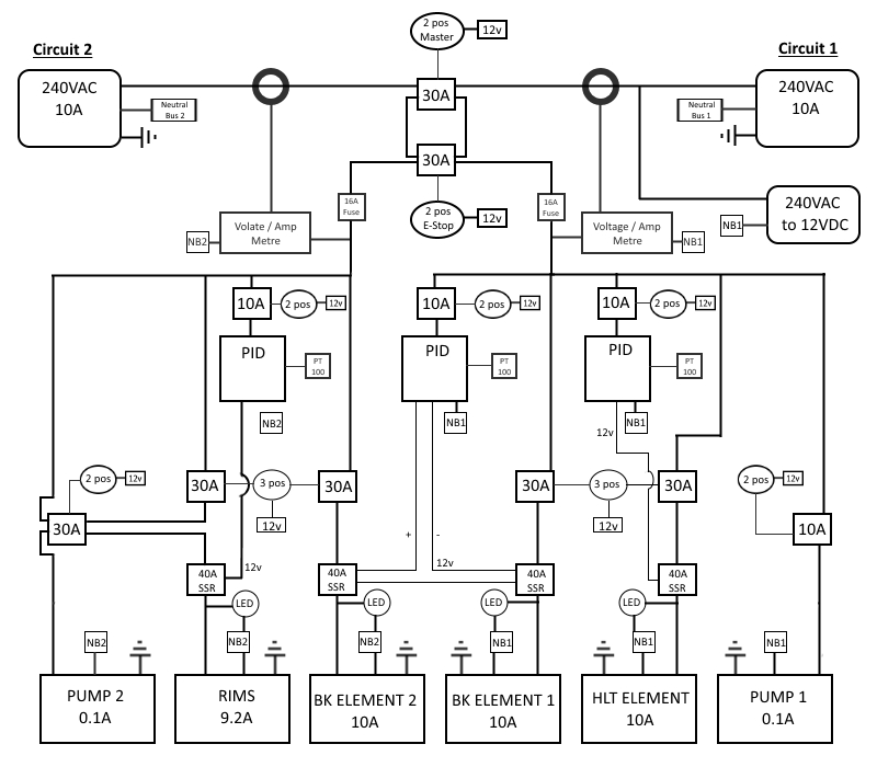
  • In order to run everything, and given that I am currently in a rental (and will be for the foreseeable future), I have two source of 10A power going into the unit, which will be run off of separate circuits in the house.
  • Each source will power only one 2200w to 2400w element at a time
  • The boil kettle will have two elements to allow for a vigorous boil.
  • Each element will be run through a 40A SSR
  • Each circuit will also run a pump (yet to dicide but from what I can tell the Keg King pumps only draw 0.1A
  • There are going to be three way switches (e.g. RIMs/BK1/OFF) for each circuit.
  • For the sake of cost and safety, I've decided to use 12vdc powered switches and relays.
  • The system is controlled by PIDs (Aubers) with the BK elements running of each circuit and controlled by the BK PID.
What I need to know is does everything look right? I'm fairly confident with wiring and electronics, but I'm not a sparky. Any advice would be very helpful.
 

Attachments

  • RIMS Plan Wiring detailed.jpg
    RIMS Plan Wiring detailed.jpg
    159.9 KB · Views: 401
Hi Bruer,
I've been a long time lurker on this site, but now first time poster.
As I've learnt so much from all the members, I figure it's time to share back.

I am a sparky and I built my own 1V system, so I'll offer some observations based upon my technical knowledge, not so much my brewing experience.

I have attached an edit of your original drawing (pretty nice work by the way, very neat, although it took me a bit to get my head around) with some areas you could make some savings.

The red circle is around your master and em-stop contactor/relays. I assume your intention is to have either the em-stop push button or your 2-pos master switch control the power to the rest of the circuit. You can do it this way, but you will have to buy two separate relays. It would be easier and cheaper to just switch the 12V coil voltage for one relay. All you would do is put the em-stop push button in series with the 2-pos master switch.

This is the same for the area in the yellow circle. I am guessing that you don't want the RIMS element to turn on unless you have the pump running. This can be achieved in a similar way to above, put the SSR control voltage through a spare contact on the pump 2 pos switch so that the SSR won't fire unless the pump is switched on. This is how I did it with my system to put the heating elements in either auto or manual.

I hope that makes sense, ask any more questions you have and I'll try my best to help.
 

Attachments

  • RIMS Plan Wiring detailed.jpg
    RIMS Plan Wiring detailed.jpg
    121.8 KB · Views: 350
Last edited:
Thanks SwagBiker.

I total agree with the main on/off and em-stop - I must've had a brain fart moment with not thinking of just wiring them in series.

The only issue with wiring the switches for the pump and RIMs in series is that i want to be able to control the pump independent of the RIMs (i want to be able to have the pump on and rims off). If I have the RIms wired through the second NO circuit (when pump is off with no power to pump relay coil) of the 30A pump relay, the the pump should work at all times and the RIMs only work when the pump is on. Unless I'm wrong?
 
Last edited:
Thanks SwagBiker.
If I have the RIms wired through the second NO circuit (when pump is off with no power to pump relay coil) of the 30A pump relay, the the pump should work at all times and the RIMs only work when the pump is on. Unless I'm wrong?

Yes, Thats called an electrical interlock.
 
That was the point of it. Open to suggestions if there is another way. All of the switches are 12V switches. Apart from the PIDs, I wanted everything on the front panel to be 12VDC. I only wanted to get the good kind of buzz from homebrewing
 
You seem to understand control wiring better than most of the domestic sparkies I've worked with.

It all looks pretty good. If you are still concerned when you finish the wiring, post some pics before you energise it. If your hands are as good as your brain though, you should be right.
 
I've been a long time lurker on this site, but now first time poster.
As I've learnt so much from all the members, I figure it's time to share back

Thanks again mate and welcome to the posting member fold.

This is the same for the area in the yellow circle. I am guessing that you don't want the RIMS element to turn on unless you have the pump running. This can be achieved in a similar way to above, put the SSR control voltage through a spare contact on the pump 2 pos switch so that the SSR won't fire unless the pump is switched on. This is how I did it with my system to put the heating elements in either auto or manual.

I'm trying to work this one out. So instead of wiring the 240VAC element active through the second circuit on the 30A water pump relay, I wire the 12VDC SSR control wire through the same NO stwitch on the Water Pump switch?
 
Sound and Safe Logic tells me that the main power to the control box should be via a mechanically operated full current switch and not a control voltage relay operation. Otherwise you risk not being fail safe if something goes wrong with the 12vdc circuit/equipment and you need to isolate in an emergency.

This is just my view from many years of investigating electrical incidents

Cheers

Wobbly
 
Sound and Safe Logic tells me that the main power to the control box should be via a mechanically operated full current switch and not a control voltage relay operation. Otherwise you risk not being fail safe if something goes wrong with the 12vdc circuit/equipment and you need to isolate in an emergency.

So a 240VAC switch? And 240VAC Em-stop? What are the pitfalls of going 12VAC with a mechanical relay? Do they fail open or closed? Given that my system will not be hardwired in or permanently plugged in, what have you seen that i should be concerned about?
 
That was the point of it. Open to suggestions if there is another way. All of the switches are 12V switches. Apart from the PIDs, I wanted everything on the front panel to be 12VDC. I only wanted to get the good kind of buzz from homebrewing
You can get 12v PIDs. there are xmt7100s available in 12v.
 
So a 240VAC switch? And 240VAC Em-stop? What are the pitfalls of going 12VAC with a mechanical relay? Do they fail open or closed? Given that my system will not be hardwired in or permanently plugged in, what have you seen that i should be concerned about?
Imo without getting into anything over the top like a sil 3 rated system a simple start/stop based ES system will be more than adequate. How about you have the 12v controlls completely run in 12v with dual supplies from both 240v circuits diode auctioneered to a single 12v supply?
 
Thanks SwagBiker.

I total agree with the main on/off and em-stop - I must've had a brain fart moment with not thinking of just wiring them in series.

The only issue with wiring the switches for the pump and RIMs in series is that i want to be able to control the pump independent of the RIMs (i want to be able to have the pump on and rims off). If I have the RIms wired through the second NO circuit (when pump is off with no power to pump relay coil) of the 30A pump relay, the the pump should work at all times and the RIMs only work when the pump is on. Unless I'm wrong?

Hey Bruer,
Sorry for my slow reply. Busy days at work and a ten yo birthday party to get through.
I’ve done a quick sketch of what I was explaining. I hope you can make sense of it, it’s drawn more like an electrical schematic, which is what I’m used to.
I also included circuit protection for the 12v power supply. The sizes of the fuses or circuit breakers will depend on the output of the power supply.
For clarity, I’ve only inlcuded the parts of the circuit that I made mention of.
I hope it helps.
 

Attachments

  • CB7ECF44-8693-43C4-9C32-0F4BD25D4D41.jpeg
    CB7ECF44-8693-43C4-9C32-0F4BD25D4D41.jpeg
    1 MB · Views: 315
Damn. Jumped the gun on that one.

Thanks swag biker and everyone. Redone my wiring diagram with all suggestions.

One question: do the 30A mechanical relays for the 12vdc switches to activate the elements need to be 30A? Can I get away with 10A relays?
 
Damn. Jumped the gun on that one.

Thanks swag biker and everyone. Redone my wiring diagram with all suggestions.

One question: do the 30A mechanical relays for the 12vdc switches to activate the elements need to be 30A? Can I get away with 10A relays?

I would leave them at 30A if you’ve already bought them.
It looks like your elements are rated to 10A each, so whilst theoretically it should be fine to use 10A relays, you won’t have any wriggle room. Everything has a manufacturing tolerance which is +/- its nominal value. If the element is slightly higher and the relay slightly lower then you’ll be stressing the relay contacts. So I’d personally avoid potential stress on the contacts as it’ll cause overheating and eventually failure. This will also be exacerbated by temperature rises inside your control box from SSRs and other components.
Go with relays around 15A to achieve a balance between economics and reliability if you haven’t bought them yet.
If you’ve already bought the 10A relays, you can also use two contacts in parallel (if your relays are two or more pole). This will effectively give you n x10A (n being the number of relay poles).
 
Hey guys, it's an old thread and I've taken all the advice on board and am well on the way to completing the wiring.

Just a quick question. Because I need to use two household circuits (separate cicuits), is it proper and safe to run all of the earths into the same bus?
 
Hey guys, it's an old thread and I've taken all the advice on board and am well on the way to completing the wiring.

Just a quick question. Because I need to use two household circuits (separate cicuits), is it proper and safe to run all of the earths into the same bus?

That is not a problem at all. Earths can be bonded together but neutrals and actives cannot.
 
Back
Top