


voodoobrew
Well-Known Member
- Joined
- 2/2/11
- Messages
- 57
- Reaction score
- 6
Hi everyone. I've been having some troubles with my SSRs for a new build.
The story is that I cannot get either of them to switch a dummy load (eg 40W lightbulb, kitchen kettle, etc). My low voltage signals happily switch the SSR causing the built in indicator LED to illuminate. But this has no effect on the 240V device attached.
Running a multimeter across the output sockets shows both 240V when the SSR is inactive and active. I understand that there will be a leak current, but thought it worth mentioning for the sake of completeness.
The SSRs themselves are common Fotek 25DA that I'm sure plenty of people have experience with.
Here is an annotated photograph of my wiring, and some explanatory notes...
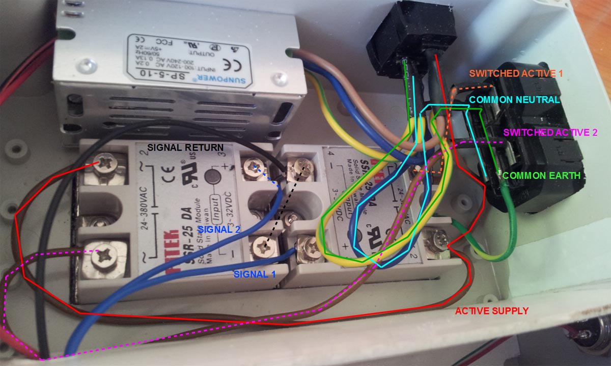
The AC comes in on the male IEC connector at the top and exits through the two female connectors on the right. I have the active switched by the SSRs before nipping out to the female connectors. The thin blue and black leads are my low voltage signal wires (3.3V).
Is this behaviour familiar to anyone? And does anyone have any thoughts why this isn't working?
The story is that I cannot get either of them to switch a dummy load (eg 40W lightbulb, kitchen kettle, etc). My low voltage signals happily switch the SSR causing the built in indicator LED to illuminate. But this has no effect on the 240V device attached.
Running a multimeter across the output sockets shows both 240V when the SSR is inactive and active. I understand that there will be a leak current, but thought it worth mentioning for the sake of completeness.
The SSRs themselves are common Fotek 25DA that I'm sure plenty of people have experience with.
Here is an annotated photograph of my wiring, and some explanatory notes...
The AC comes in on the male IEC connector at the top and exits through the two female connectors on the right. I have the active switched by the SSRs before nipping out to the female connectors. The thin blue and black leads are my low voltage signal wires (3.3V).
Is this behaviour familiar to anyone? And does anyone have any thoughts why this isn't working?