Motion Dynamics Mill Motor Wiring

Australia & New Zealand Homebrewing Forum

Help Support Australia & New Zealand Homebrewing Forum:

Crusty

Well-Known Member
Joined
29/6/08
Messages
2,623
Reaction score
607
Location
Gulmarrad, NSW
Hey guys.
After owning my mill motor for well over a year & still sitting in the box, I thought it might be time to wire it up. I've followed a few examples on the net but I can't seem to get power from the power supply to the mill motor.
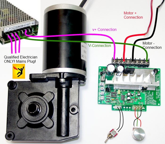
Could someone drop some photos in here describing what wire goes where. I've wired up the 240V side so the power supply powers up, the red motor wire in top port of green pcb board, black motor wire to the bottom of the pcb board but I'm stuck there.
I've got this power supply,

344878.jpg
 

RRising

Well-Known Member
Joined
11/7/18
Messages
295
Reaction score
81
Location
Adelaide
Can you post an actual photo of your motor and wiring?

Are you having trouble with the power supply side or motor side wiring?

I found this... might be what you are looking for.

Brewer3.jpg


From what i can gather, pink line is positive and green is negative.
 
Last edited:

Crusty

Well-Known Member
Joined
29/6/08
Messages
2,623
Reaction score
607
Location
Gulmarrad, NSW
I looked at that but my PSU is different.
From the left of mine, I have +V for three ports, -V for the next three ports then E,N,L. I would assume one wire goes to the +V & the other to the-V but not too sure where those wires then go on the green pcb board. I've got it wired different to above so I might do what is done there. I'll give it a go.
Cheers
 

Crusty

Well-Known Member
Joined
29/6/08
Messages
2,623
Reaction score
607
Location
Gulmarrad, NSW
Can someone that's wired up their Motion Dynamics mill motor show me what wires they put where from the variable speed pot to the little green board. I've tried wiring it up in so many configurations but the motor just runs flat out, no speed control at all. I'm starting to think I have a faulty board.
 

Crusty

Well-Known Member
Joined
29/6/08
Messages
2,623
Reaction score
607
Location
Gulmarrad, NSW
Don't know if you have already looked at this Crusty

Thanks for that. That's the package I have.
I just can't seem to get the speed control to work. The potentiometer is fine, I've measured resistance with a volt meter & it works but when I wire it up to the PC board, nothing, no matter in which configuration I wire it.
 

Crusty

Well-Known Member
Joined
29/6/08
Messages
2,623
Reaction score
607
Location
Gulmarrad, NSW
Give them a ring tomorrow

Will do but there's shit loads of people on here that have wired them up & was hoping to get some insight. I'm stumped with what's going on. It's wired correctly as far as I can tell & I'm a bit suspicious that my board is cactus.
 

wide eyed and legless

Well-Known Member
Joined
5/9/13
Messages
7,273
Reaction score
3,529
Location
Mulgrave Victoria
Best way to look for old threads is through Google. I was going to suggest Jaycar if there was one near you, but they will be in lockdown the guys there a pretty helpful.
Just Google motion dynamics Aussie Home Brewer, tried to link it but it didn't work.
 

Crusty

Well-Known Member
Joined
29/6/08
Messages
2,623
Reaction score
607
Location
Gulmarrad, NSW
Best way to look for old threads is through Google. I was going to suggest Jaycar if there was one near you, but they will be in lockdown the guys there a pretty helpful.
Just Google motion dynamics Aussie Home Brewer, tried to link it but it didn't work.

Yeah, tried all that.
Cheers
 

RRising

Well-Known Member
Joined
11/7/18
Messages
295
Reaction score
81
Location
Adelaide
Can someone that's wired up their Motion Dynamics mill motor show me what wires they put where from the variable speed pot to the little green board. I've tried wiring it up in so many configurations but the motor just runs flat out, no speed control at all. I'm starting to think I have a faulty board.

Have you got it on the right jumper settings?

speed_control_pcb6.png


According to this, you need it on J1 2-3 for the potentiometer.
 

Crusty

Well-Known Member
Joined
29/6/08
Messages
2,623
Reaction score
607
Location
Gulmarrad, NSW
I'm not sure. I have it wired to the same three ports as in the picture.
The bottom three ports on the left. The motor works fine just no speed control.

IMG_1876.JPG
 

Crusty

Well-Known Member
Joined
29/6/08
Messages
2,623
Reaction score
607
Location
Gulmarrad, NSW
Do I need to have a switch inline to possibly power the pot? Maybe that's the problem. If I don't wire a switch in, can I just use a jumper lead into the top block?
Where my thumb is, out the top & in the bottom of the same block, the very top one.
 

MHB

Well-Known Member
Joined
1/10/05
Messages
6,924
Reaction score
4,421
Location
Newcastle
On the right hand side, numbering the terminals from 1-8 top down.
In the drawing they have a jumper from 1-2 and 7-8, I cant see the same on your board, it might be that the control isn't being powered.
Mind you I'm OK with wiring power but electronics isn't really my thing.
Mark
 

Crusty

Well-Known Member
Joined
29/6/08
Messages
2,623
Reaction score
607
Location
Gulmarrad, NSW
On the right hand side, numbering the terminals from 1-8 top down.
In the drawing they have a jumper from 1-2 and 7-8, I cant see the same on your board, it might be that the control isn't being powered.
Mind you I'm OK with wiring power but electronics isn't really my thing.
Mark

Thanks Mark.
It's so bloody confusing. This came with it as the instructions, different again. I don't think you need the jumper wires for 30A, according to instructions it's for 50A as ports 1,2 are the same, 3,4 are the same etc.
IMG_1877.JPG
 

Crusty

Well-Known Member
Joined
29/6/08
Messages
2,623
Reaction score
607
Location
Gulmarrad, NSW
I ran a jumper lead into that first terminal block & a green light activates so there's power but still no bloody speed control.
 

Crusty

Well-Known Member
Joined
29/6/08
Messages
2,623
Reaction score
607
Location
Gulmarrad, NSW

Latest posts

Top