Arduino Development Thread

Australia & New Zealand Homebrewing Forum

Help Support Australia & New Zealand Homebrewing Forum:

This site may earn a commission from merchant affiliate links, including eBay, Amazon, and others.
Bonj is on the money (as usual)

My ones came with this blurb

Output leads: red (VCC), yellow (DATA), green (is) (GND)


The probe of this temperature sensor is DS18B20 original chip
High quality stainless steel tube
Waterproof and corrosion-resistant
Shell size: 6 mm (Diameter), Length of Cable: 100 cm
Power supply range: 3.0V to 5.5V
Temperature range: -55C to +125C (-67F to +257F)
Accuracy: 0.5C (-10C to +85C)
No other components, unique single bus interface
 
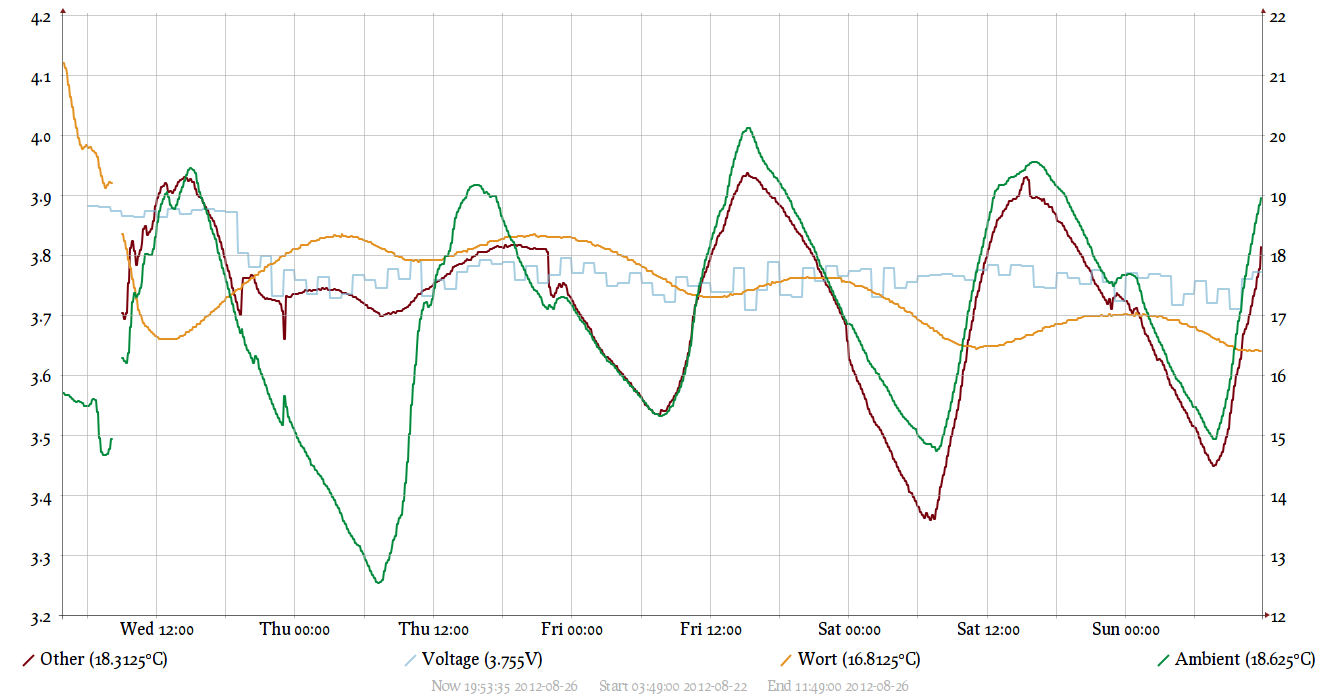
I've got my ambient fermenter temperature logging over bluetooth going. It's an atmega328 (not arduino, since I already have plain AVR stuff), talking bluetooth to my home router with OpenWRT, then to a webserver. Kind of overkill, yes :rolleyes:. Runs off 3xNiMH batteries, lasts about 3 weeks (should be more, need to measure what's using too much current). I'm using DS18B20 sensors, one in a Brewers Hardware thermowell. It's a Dealextreme $6 bluetooth module, think wavesen.com make them. Source here.

templog2.png

The right axis is temperature, left is battery voltage. The live site lets you zoom in, click the left axis to zoom out.
 
Sounds like someone was inspired by uberfridge. :)
Looks good. There looks to be a lot of variation in the wort temp, but can't do much without a fermentation fridge.
 
Nice graph! That graph is pretty much what i'm aiming for as the end result, with a little more info (such as fridge air temp), over two fridges.
 
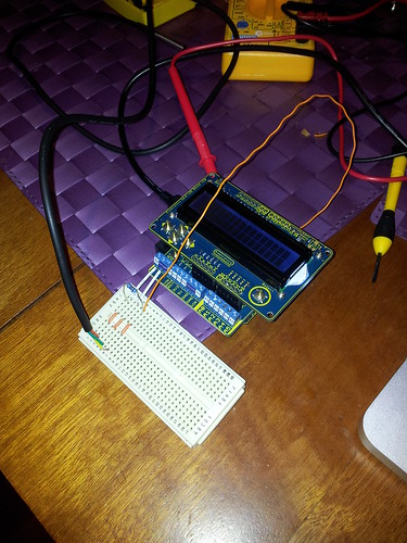
Been off work today looking after a crook kid, so took the chance to play with the OneWire sensors.

Quite easy to work with, especially considering I have very little electrical knowledge.


ArduFerm OneWire by auvortex, on Flickr
 
Been off work today looking after a crook kid, so took the chance to play with the OneWire sensors.

Quite easy to work with, especially considering I have very little electrical knowledge.


ArduFerm OneWire by auvortex, on Flickr

Isn't it nice when things just work!

Spare no expense with those freetronics things...

Doesn't that LCD and keypad module take up a lot of pins?
 
So, sprintf() on Arduino doesn't deal with floats so well - I still get ? marks when printing a float. Does anyone have a workaround for this? Or is the workaround to just not use sprintf()? Some googling shows this has been an issue for a long time, but was supposed to be fixed in Arduino 0013 - but I guess that fix didn't cover sprintf().
 
So, sprintf() on Arduino doesn't deal with floats so well - I still get ? marks when printing a float. Does anyone have a workaround for this? Or is the workaround to just not use sprintf()? Some googling shows this has been an issue for a long time, but was supposed to be fixed in Arduino 0013 - but I guess that fix didn't cover sprintf().
Hmm... I can't say that I've noticed floats not working. Although I can't remember if I've used floats with it on arduino....

Perhaps try strcat?
 
Long time stalker in the Arduino thread...

I just picked up an etherten a couple of weeks ago and got it talking on my lan the other night which is more than I could do with the cheap evilbay ardiuno and ethernet shield I was banging my head against a wall with...

Isn't it nice when things just work!

Spare no expense with those freetronics things...

Doesn't that LCD and keypad module take up a lot of pins?


am I missing something?

http://www.freetronics.com/products/lcd-ke...ld#.UD3Pz6PN1Ns

states the LCD shield uses one analog input for the buttons and 6 digitals for the LCD? or do you guys use serial for LCD?
 
I use an I2C LCD, which means zero digital pins required!
If I were to pair this up with analog buttons then I would have all digital pins available still!

:)
 
I use an I2C LCD, which means zero digital pins required!
If I were to pair this up with analog buttons then I would have all digital pins available still!

:)
I use the 4bit mode for the LCD on my HERMS PCB, 6 pins there. I also use the analog pins in digital mode (digital pins 14-19) for my pushbuttons.... but it seems that I used pins for the LCD connection that conflict with the ethernet shields, so the next revision (if I have any interest from others) will be more compatible.

I have made some real progress on the HERMS controller this week. I now have working config menus, and working step mashing... with configurable steps. Just working on the PID tuning config menus/eeprom saving/reading, and same for loading and saving custom mash programs.... but as it stands now, it is a working HERMS controller :D
 
hey guys... just soldered mine together and wanted to test the LCD and see if I could get it talking to me. I plugged it into the computer and she boots up fine... the LCD comes on but when I try to use one of the example 'Hello World' sketches it doesn't do anything. I've changed the pins to 2,3,4,5,6. Anything else I'm missing?
 
hey moosebeer,

the code should read
Code:
LiquidCrystal lcd(2, 3, 4, 5, 6, 7);

and in 'setup'

Code:
lcd.begin(16,2);

let us know if you have anymore problems

cheers steve
 
Thanks Matho... I did actually have that code in there but went back and realised there may have been a few dodgy solder joints so fixed those up and am now getting my LCD to display text. It's hard to read though... the 2x16 white squares on the display are too bright to be able to read the text properly.

Edit... just looked over the schematics and realised that the 5k pot is my answer!
 
Thanks Matho... I did actually have that code in there but went back and realised there may have been a few dodgy solder joints so fixed those up and am now getting my LCD to display text. It's hard to read though... the 2x16 white squares on the display are too bright to be able to read the text properly.

adjust the trim pot (the blue thing up near the LCD) that is the contrast control just turn in back and forth until you find what looks best

cheers steve
 
It Lives!

20120830_130501.jpg

While my original design goals have now been accomplished:

Multiple steps with independent temperature set points and times.
PID controlled temperature
Preset commonly used mash programs
Custom mash program entry, saving and loading (to/from EEPROM)
PID tuning parameter entry, loading and saving (EEPROM)

I can't help feeling the need to implement PID autotuning with the arduino PID autotuning library....
 

Latest posts

Back
Top